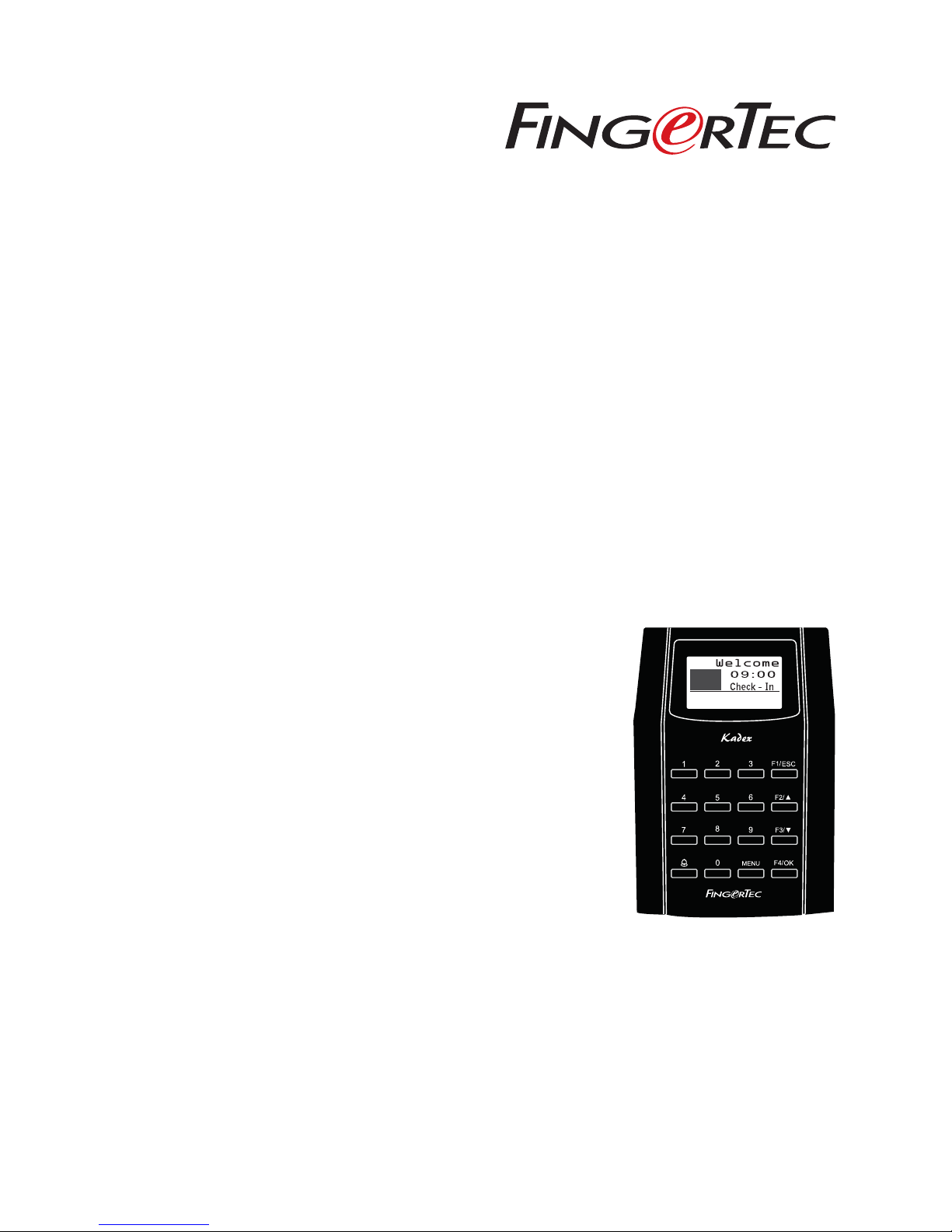
FingerTec Kadex User manual
w
13-01-01 MON
Kadex
Standard RFID Card Door Access Control &
Time Attendance System
User Guide

CONTENTS
3-4 CHAPTER 1 •
GETTING STARTED
Viewing the User Guide in the Internet
Terminal Included Accessories
Included Printed Materials
Activating Terminal
Registering Terminal
5-7 CHAPTER 2 • BASICS
Introduction to Products
Overview
Power On/Off Button
Keypad
Battery
Date/Time
Voice Control
Security Features
Cleaning Terminal
Restarting and Resetting Terminal
8-13 CHAPTER 3 • CONNECTION
– SYNCING TERMINALS
Installations
Communications
Ingress Online Activation
Installation and Setup of Ingress
Connecting Terminals to Ingress
Using USB to Download/Upload Data
Communication Key
14-15 CHAPTER 4 • USER
Enrolling User
Types of Verification Method
Adding User Information
Deleting User
Access Level/Privilege
15-19 CHAPTER 5 • SYSTEM
General Settings
Update Firmware
System Information
Log Information (Log Opt)
CONTENTS
20 CHAPTER 6 • DATA
Deleting Transaction Logs
Deleting All Data
Managing User Privilege
Resetting to Factory Settings
21 CHAPTER 7 • USB
Understanding the Need for USB Flash Disk
Type of USB
Downloading Attendance Logs
Downloading User Data
Uploading User Data from USB to Terminal
Uploading Short Messages
22-25 CHAPTER 8 • ACCESS
Using The Terminal as Door Access
Access Options
User Account Options
Access Combination
Lock
Door Sensor Delay
Door Sensor Mode
Door Sensor Alarm
Turning Off Alarm
Duress Options
Alarm Count
Group Verification Type
26 CHAPTER 9 • RFID CARD FUNCTION
Enrollment of RFID Card
Verification Using RFID Card Only
Multi Verification Methods Using RFID
Deleting RFID Card
Changing Card ID
27 CHAPTER 10 • HID CARD FUNCTION
Registering HID Card
Deleting HID Card
28 CHAPTER 11 • AUTO TEST
Who Should Do The Auto Test?
Run All Tests At Once
FLASH Test
LCD Test
Voice Test
Key Test
RTC Test
29 TROUBLESHOOTING

3
USB Extension
To connect to the USB port of
a computer for uploading and
downloading of data.
Screwdriver
Use the screwdriver to open the
back plate of the terminal and
to install the back plate against
a wall.
TCP/IP Connector
Connecting the network cable
from a PC or Network switch
to a TCP/IP connector at the
terminal.
TCP/IP Cable
Connecting terminal for
Ethernet connection.
A Packet of Bolts
Use the screws to hold the
back plate of the terminal
against a wall.
RFID Cards (5 pieces) /
HID/MIFARE Cards (1 piece)
For card enrollment and
verification.
Door Accessories Cable
Cables for 12V door lock, push
button, 12V alarm, door sensor
and 12V door bell, for door ac-
cess.
RS232/RS485/Wiegand
Output Cable
For serial cable connection and
Wiegand Output connection.
Power Supply Cable
To connect the terminal to a
12V power supply.
w
13-01-01 MON
CONTENTS
1• GETTING STARTED
Viewing the User Guide in the Internet
The User Guide is available in the package when you purchase the terminal. The User
Guide is also available online at fingertec.com and user.fingertec.com. Choose the lan-
guage that you prefer for your online User Guide.
Terminal Included Accessories

4CONTENTS
Included Printed Materials
• FingerTec Comprehensive DVD
• Quick Start Guide
• User Enrollment Template Form
• Warranty Card
Activating Terminal
Every FingerTec access control model comes bundled with a unique license key. To
start using the terminal with Ingress, you must connect the terminal to Ingress and
perform online activation. Ingress reads the serial number of your terminal and sends
it for verification at the FingerTec server via Internet.
In case you do not have an Internet connection, you would need to do offline activa-
tion. Please send the serial number and models of your terminals to your local resellers
or [email protected] to request for a product key and activation key.
Registering Terminal
Make sure that you register your terminal’s warranty with us at fingertec.com/ver2/
english/e_warranty.htm.
5
w
13-01-01 MON
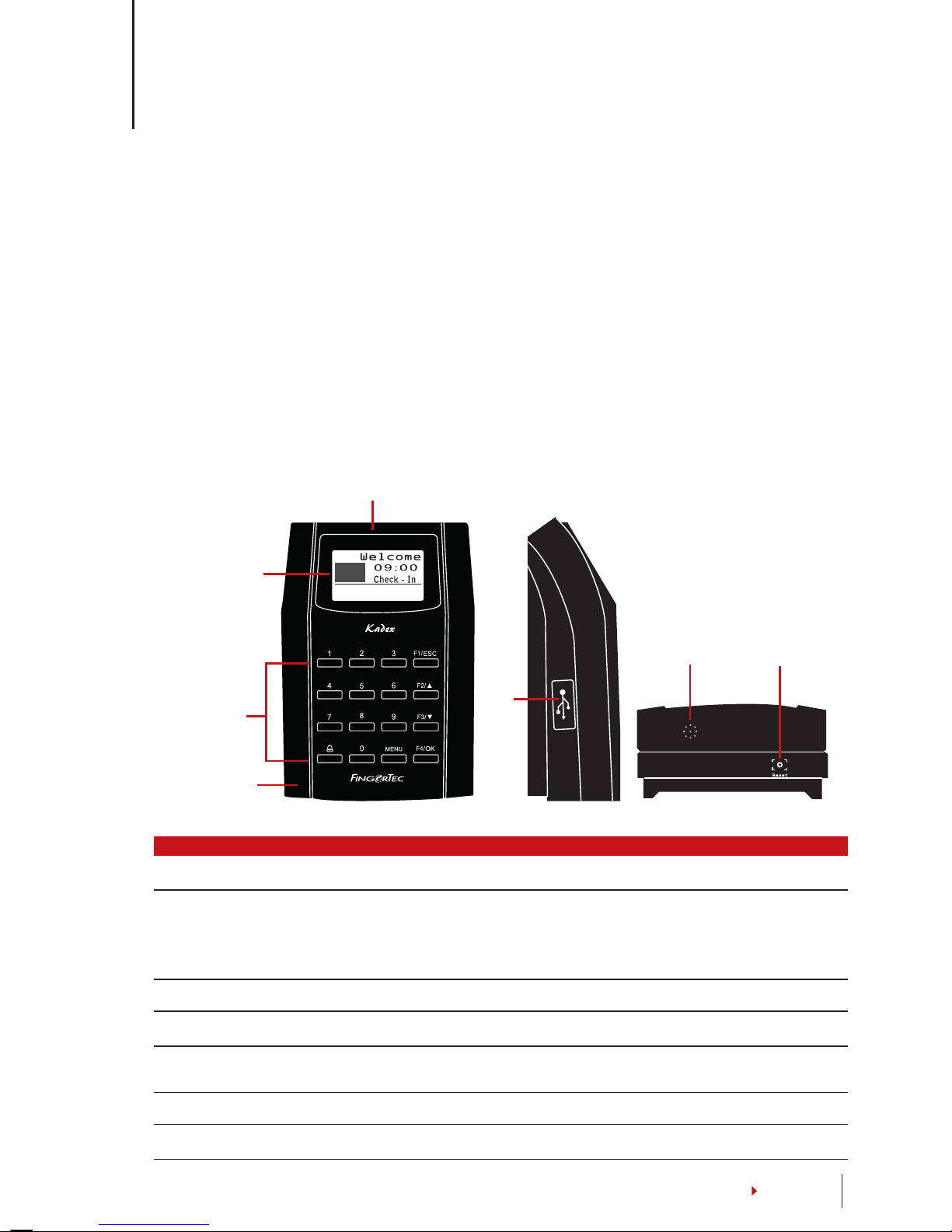
L.E.D Display
LCD Screen
Keypad
Card Induction
Area
USB
Port
Reset Button
Speaker
CONTENTS
2 • BASICS
Introduction to Products
The terminal for time attendance and door access system supports RFID card ID, 5-digit
password or combination of both. It works with security alarm system to alert users in
cases of break in and when the duress function in the terminal is used. The terminal can
integrate with a fire alarm system to unlock all doors when the fire alarm is triggered.
The terminal communicates with a computer via TCP/IP and it allows data transfer to be
done with USB flash disk to eliminate extra wiring.
The terminal complies with international standard of CE & FCC, our testament to safety
& quality.
Overview
ITEM FUNCTION
LCD Screen Displaying status of terminal, day, date and time.
LED Display Green LED – The terminal is working fine and it is in standby mode.
Red LED – There is an error at the terminal that requires checking.
For first time use, the terminals need to be charged fully to avoid
having the red light blinking.
Keypad To input instructions into the terminal and to allow configuration.
RFID Card Induction Area Area that reads RFID cards.
USB Port To upload/download users information, password and transaction
logs via USB flash disk.
Speaker For terminal voice emission.
Reset Button To restart the terminal as and when required.

6CONTENTS
Power On/O Button
There is no power button available. Restart the device using the reset button shown on the
bottom of the terminal.
Keypad
You can insert inputs into the terminals through
the keypad. It contains numbers from 0-9, an OK
button, an ESC/Cancel button, a Scroll up/down
button, a doorbell button and a Menu button.
Battery
The terminals operate using power supply from a standard power outlet.
Mini UPS: Mini UPS 12V can also be used to provide power supply to turn on the ter-
minals. Refer to accessory.fingertec.com for more information about accessories.
Date/Time
The terminals displays the date and time at the home screen. Choose the date and
time format based on your preference. Press Menu > Options > Systems Options >
Date/Time > set your time and save.
To change the date format: Press Menu > Options > Systems Options > Fmt > Deter-
mine the date format based on your preference.
Voice Control
Voice Control lets you control the level of volume emitted by the terminal.
TURN ON/OFF
The system lets you turn on/off the voice based on your preference. Press Menu >
Options > System Option > Adv Option > Voice > Y/N.
ADJUST VOLUME
The default volume of the terminal’s voice is 67. The volume can go as high as 100
and as low as 0. To sustain the performance of the speaker, it’s recommended to stay
at range 60-70. To adjust the volume Press Menu > Options > System Option > Adv
Option > Adj VOL (%) > adjust accordingly .

7
CONTENTS
Security Features
Security features help protect the information in the terminal from being accessed by
unauthorized individuals.
ADMIN AFFIRM
Register an administrator into the system by enrolling or a password to a user ID. Press
Menu > User Manage > Enroll Admin > Choose enrollment method > Perform enrol-
ment and Save. After enrolling an administrator, the main menu can only be accessed
by the administrator.
TAMPER SWITCH
The terminals come with a tamper switch located at the rear of the terminals. During
installation, the tamper switch is compressed against the back plate. Any attempt to
dismantle the terminal will trigger an alarm and a “System Broken” message will be
displayed on the panel.
Cleaning Terminal
CLEANING THE BODY
Use a dry cloth to clean the terminal’s body. Do not use any liquids, household clean-
ers, aerosol spray, solvents, alcohol, ammonia and abrasive solutions to clean the body
of the terminal because it could damage it.
Restarting and Resetting Terminal
If a feature isn’t functioning as it should, try restarting or resetting the terminals
RESTARTING THE TERMINAL
Push the On/Off button or “reset button” on the terminal to restart the terminal. If you
can’t restart the terminal, or if the problem persists, you might want to reset.
RESETTING THE TERMINAL
Press Menu > Option > System Option > Adv Opt > Reset terminal. Resetting of the
terminal will cause all your settings to return to its original factory settings. Make sure
that you have backed up all data before you proceed.
8
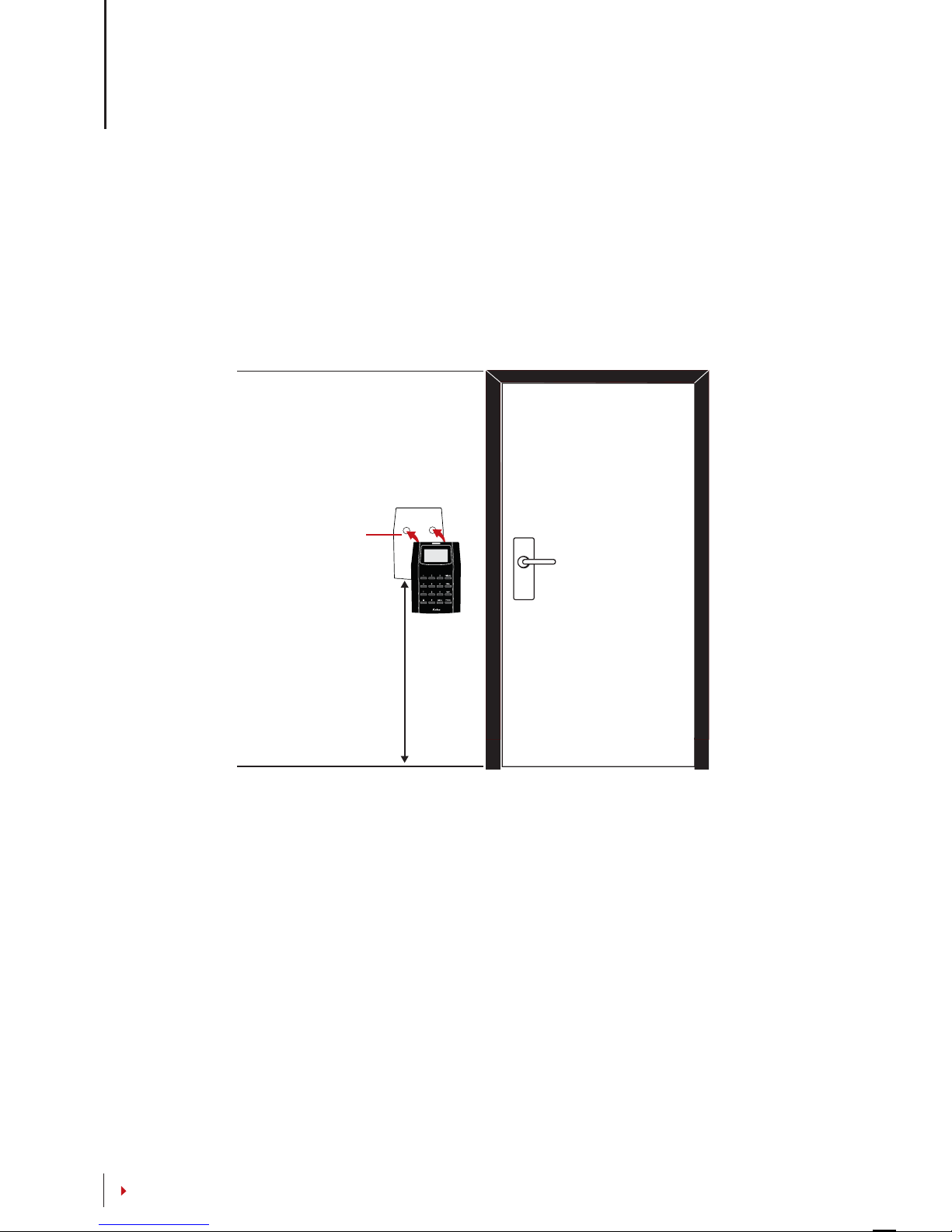
Back Plate
4 feet / 1.2 meter
(recommended)
CONTENTS
3 • CONNECTION – SYNCING TERMINALS
Installations
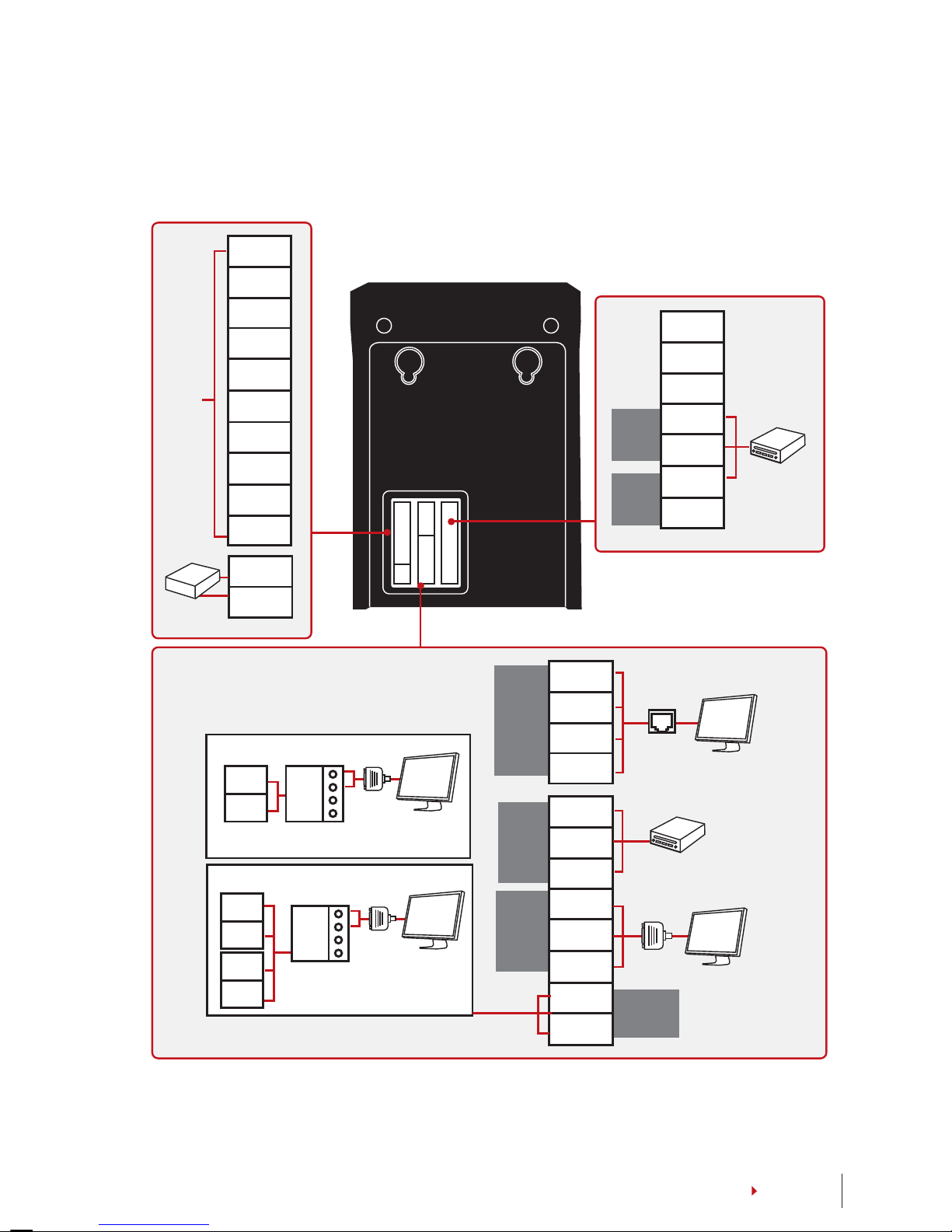
FingerTec terminals offer several connections for power and communications. Installa-
tions of FingerTec time attendance terminals are simple.
MOUNT ON WALL
Attached the back plate on the wall securely and attach the terminal to the back plate
when mounting it on the wall.
9
.
.
.
.
.
.
.
.
.
.
.
.
.
.
.
.
.
.
.
.
.
.
.
.
.
.
.
.
.
.
.
.
.
.
.
.
ALM+
ALM-
NC
COM
NO
BUT
GND
SEN
BEL+
BEL-
GND
+12V
DC12V
Power Supply
For NC
or NO
door
lock
system
BEEP
GLED
RLED
INWD0
INWD1
GND
+12V
Wiegand
IN
Power
OUT
3rd party
controller
with 26 bits
wiegand
output
485+
485-
485+
485-
RX+
RX-
RX+
RX-
1. RS485 Single Connection
RS232/RS485
Data Converter
RS232/RS485
Data Converter
2. RS485 Network Connection
485+
485-
RJ45-1
RJ45-2
RJ45-3
RJ45-6
WD0
WD1
GND
RXD
TXD
GND
485+
485-
TCP/IP
Wiegand
OUT
RS232
3rd party controller
with 26 bits
wiegand input
RS232
cable
TCP/IP
RS485
CONTENTS
Communications
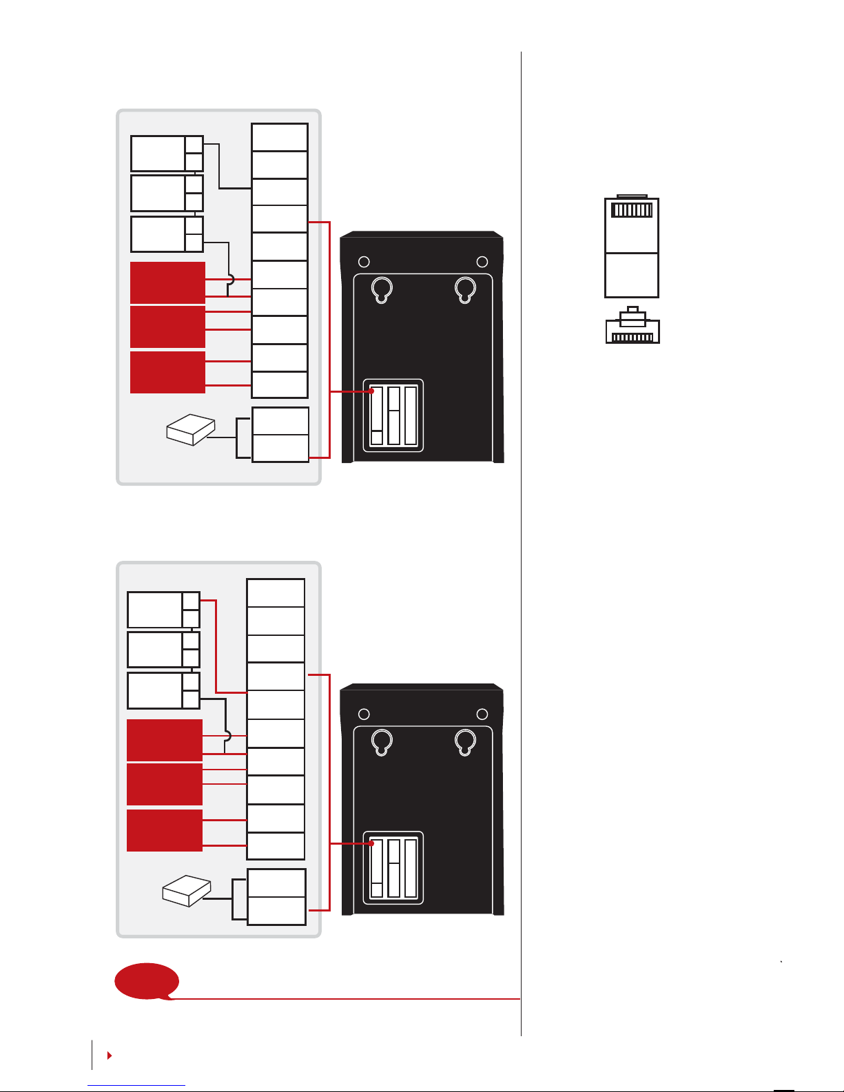
Connection points for power and communication are available on top of the terminals.
Refer to the following diagrams for the terminals you require.
10
.
.
.
.
.
.
.
.
.
.
.
.
.
.
.
.
.
.
.
.
.
.
.
.
.
.
.
.
.
.
.
.
.
.
.
.
.
.
.
.
.
.
.
.
.
.
.
.
.
.
.
.
.
.
.
.
.
.
.
.
.
.
.
.
.
.
.
.
.
.
.
.
ALM+
ALM-
NC
COM
NO
BUT
GND
SEN
BEL+
BEL-
GND
+12V
DC12V Power Supply
Release
button
Door
sensor
Doorbell
+
-
2
3
A
C
EM lock
(NC)
Emergency
break glass
(NC)
Key switch
(NC)
ALM+
ALM-
NC
COM
NO
BUT
GND
SEN
BEL+
BEL-
GND
+12V
Release
button
Door
sensor
Doorbell
+
-
1
3
B
D
EM lock
(NO)
Emergency
break glass
(NO)
Key switch
(NO)
NOTE Please refer to AdapTec AC Installer Manual if you are
using AdapTec AC.
DC12V Power Supply
1 8
TOP
FRONT
1 8
CONTENTS
For NC (normally closed) door lock system
For NO (normally open) door lock system
USB PORT
Linking with USB flash disk
for remote data
transfer.
TCP/IP PORT
Connect with CAT 5 cable
for LAN connection, one
end to this port and an-
other end to the compu-
ter’s TCP/IP Port.
TCP/IP for Single Connec-
tion – Linking the terminal to
a single computer using TCP/IP
requires Ethernet 10/100Base-
T Crossover Cable. The cable
can be used to cascade hubs
or to connect Ethernet stations
back-to-back without a hub. It
works with both 10Base-T and
100Base-TX
Other manuals for Kadex
2
Table of contents
Other FingerTec Gateway manuals


Popular Gateway manuals by other brands

LST
LST M500RFE-AS Specification sheet

Kinnex
Kinnex Media Gateway quick start guide

2N Telekomunikace
2N Telekomunikace 2N StarGate user manual
Mitsubishi Heavy Industries
Mitsubishi Heavy Industries Superlink SC-WBGW256 Original instructions

ZyXEL Communications
ZyXEL Communications ZYWALL2 ET 2WE user guide

Telsey
Telsey CPVA 500 - SIP Technical manual