Page 4 of 20 Power Supply Unit Installation & Operation Instructions FM 3020541
07/08 P/N E06-052 Rev. 9
4.0 INSTALLATION
4.1 INSTALLATION OVERVIEW
The effectiveness of active explosion protection
systems, such as explosion suppression and
explosion isolation, depends upon the instantaneous
reaction of the protection system and is a direct
function of its speed of response.
It is therefore, critical that all possible measures are
taken to reduce the individual system components’
response times to an absolute minimum.
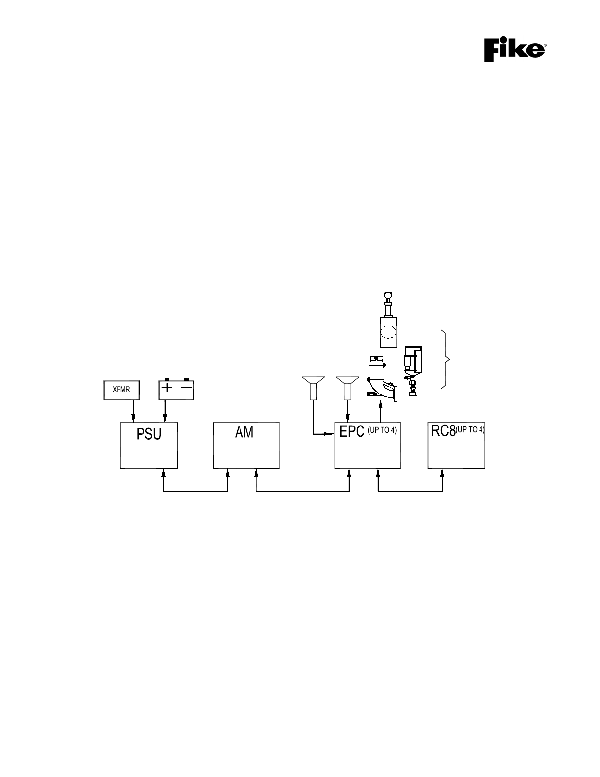
An active explosion protection system basically
consists of three components: One or more
explosion detectors, an electronic system controller,
and one or more protective devices such as
explosion suppressors or isolation valves.
Instrumentation wiring interconnects these
components.
The system controller is microprocessor-based and
shall be installed in a location that maintains the
EPC’s temperature rating of -18°C to 43°C (0°F to
110°F) when it is installed in an auxiliary housing.
For FM Approved installations the housing shall be a
lockable enclosure conforming to the installed area
requirements as defined by NEMA 250 “Enclosures
for Electrical Equipment (1000 Volts Maximum).”
Besides its function as a fire controller it also
incorporates an event table and a self-checking
feature to continuously monitor the complete
system-loop for errors or system defects.
Electronic devices, microprocessors, pyrotechnic
initiators, and field wiring are influenced by the
electromagnetic “environment” surrounding these
components. The use of cellular telephones,
transmitters, induction motors, welding equipment or
the presence of power cables and transformers can
create environments with high levels of
electromagnetic radiation, resulting in induced
electrical “noise” or voltage peaks.
Such effects are known to designers and
manufacturers of instrumentation and control
systems (PLC’s), used in industrial environments
and are handled through the use of specially
designed electronic filters. These filters neutralize
the unwanted noise and offer a “clean” signal for
further processing. The filters, however, result in a
delay in the processing of signals, and can therefore
only be applied with great care in explosion
protection systems where the effectiveness depends
on the overall response time.
In active explosion protection systems, a balance
must be maintained: The system must be extremely
fast to achieve the required effectiveness, but at the
same time must be stable and insensitive to
surrounding sources of noise.
The system controller will detect and report major
system troubles (such as ground faults, wire
disconnection, and unstable input or output signals)
and indicates the need for appropriate action.
The system controller will also detect unacceptable
levels of electromagnetically induced noise. If the
magnitude of the noise is such that this may result in
a risk for spontaneous system activation or affect the
system’s performance, the controller will revert to its
default error-mode.
It is essential to practice extreme caution when
selecting component location, cable specifications,
cable routes, and the “cleanliness” of the offered
power source. In order to reduce the
electromagnetic induced noise to a level that will not
affect the required performance of the explosion
protection system, verify all earth connections. It is
preferred to have the enclosure and conduits
connected to Protective Earth (similar with other
building grounds) while the drain wires from the field
wiring and each module ground connected to a
separate Instrument Earth. This Instrument Earth
connection shall not have inductive or capacitive
loading such as motors, welders, or other industrial
equipment. Where a separate earth connection is
not available, the drain wires and module ground
connections should be made to battery common.
Complying with the following recommendations will
help minimize the induced noise.
4.2 POWER SPECIFICATIONS
The AC supply (commonly supplied to the EPACO
Power Supply Unit, PSU) shall be wired through a
dedicated circuit to a 1002/120/240VAC 15 or 16
Amp circuit breaker. High voltage circuits may NOT
be run in the same conduit as low voltage circuits.
Cabling from transformer to PSU shall be 2.08 mm2
(14AWG) minimum not to exceed 3 meters (10 feet).
Cabling from PSU to EPC shall be 0.8 mm2
(18AWG) minimum not to exceed 10 Ω resistance.
A keyed selector switch is recommended in the PSU
to EPC power supply cabling to facilitate reset of the
EPC. This shall have a 30V, 1A rating.
2Not FM Approved for 100 VAC.