
FibroPool FH 270 Service manual


1. App aranc
1. WARNING
●Pl as install th unit in complianc with local CODES, r gulations and standards;
●Please use a solid base, such as 2 pieces of 16” x 16” x 4” concrete blocks or an equipment
base of 16” x 32 inches minimum size
●Confirm power voltage and frequency; 208-240 volts, 60 Hz 20 Amps
●2 Hot Leads, 1 Ground No Neutral, Non GFCI Within 50 feet of the breaker box, use 12 AWG
gauge wire ( 12-2+ Ground), 50-150 feet distance from breaker box to the heater, pls use 10
AWG wire ( 10-2+Ground)
●The heater must be BONDED to a ground rod, using #8 AWG bare copper wire
●An external timer or a service disconnect must be installed in accordance with local electric
codes
●1 1/2” schedule 40 pvc must be used to connect plumbing
●WATER AND ELECTRICITY DONT MIX PLEASE USE ALL PRECAUTIONS AND DO NOT
SHORT CUT ANY SAFETY PROCEDURES
●Do not install this heater in an enclosed room Without adequate air supply, the heater will not
function well If the unit was installed in a closed area or limited space, please consider the size
of room and ventilation to prevent suffocation caused by refrigerant leakage
●Be sure to Install a BONDING wire to a ground rod, using #8 AWG Bare Copper Wire
●Fibropool FH 270 is weatherproof and designed to be outdoors But is is not designed to be
below eaves of the roof, where water pours onto it Please use common sense in choosing a
location
●Do NOT install this heater where there may be flammable gas
●This heater is made of mostly metal alloys, and may have sharp edges, please use gloves while
handling it
●Heater weighs about 150 lbs It is a 2 person handling size and weight
V-2105 Fibropool Co LLC, Ms USA

Syst m Sp cifications
1. Sp cifications
Model FH 270
82'F Air 82'F Water 82% RH
Max Heating capacity (Btu/h) 70000
Max Power input (Btu/h) 12132
COP 5 77
60'F Air 75'F Water 65%RH
Heating capacity (Btu/h) 33440
Power input (Btu/h) 8360
COP 4 01
Power supply 208-230V/60Hz
Max power input (Btu/h) 13850
Max current (A) 17 7
Setting temperature range (Heating) 60°F~99°F
Setting temperature range (Cooling) 50°F~82°F
Running (Air) temperature range 23°F~109 4°F
Refrigerant type/quantity (Oz) R410A/ 48 Ozs
Air side heat exchanger Hydrophilic fin exchanger
Water side heat exchanger Titanium tube heat exchanger
Water flow (gpm) 33 GPM
Net dimension LxWxH (inch) 37 x 14 x 32
Packing dimension LxWxH (inch) 41 x 17 x 33
Net weight (lbs) 146 lbs
Packing weight (lbs)196
Noise level dB(A) 47
Water proof level IPX4
Water pipe connection PVC Sch 40 1-1/2”
Inlet/Outlet
The technical specification of our heat pumps is provided for information purpose only We reserve
the right to make change without notice in advance
Performance varies greatly depending on the weather conditions
1 Ratings based un US Dept Of Energy guidelines, 82-82-82 / 80-80-80/ 78-78-78
2 US Dept Of Energy recommends pool water temperatures 78, 80, or 82 Degrees
1 Noise at 4 feet ) comply with Directives EN ISO 3741 and EN ISO 354
V-2105 Fibropool Co LLC, Ms USA

1. Unit Dim nsions
Mod l: Fh 270
Unit:in
V-2105 Fibropool Co LLC, Ms USA

1. Explod d Vi w
1 Front plate 9 Middle plate 17 Chassis component
2 Fan 10 Water flow switch 18 Silencer cotton
3 Stand pillar 11 Titanium heat exchanger 19 Motor
4 Protection net 1 12 Right plate 20 Motor support
5 Protection net 2 13 Controller box
6 Evaporator 14 Handle
7 Electrical box 15 Cooper pipe component
8 Top cover 16 Compressor
V-2105 Fibropool Co LLC, Ms USA

Installation Instructions
WARNING: Installation must be carried out by a qualified person
This section is provided for information purpose only and may vary depending on your location/
regulations/ availabl spac for installation
1. Pr -R quir m nts
Needed equipment for installation of heat pump:
Suitable power supply cable for unit’s power Usually 12-2+Ground protected by flexible conduit
A by-pass kit ( 3 way valve) , PVC pipe and fittings, Pipe cleaner/ primer, Medium Bodied Glue
Electrical tools, and a ,multimeter
A service disconnect or timer within 6 feet of the heater
An equipment pad, 16” x 32” x 4” thick or 2 pieces of concrete blocks, 16 x 16 x 4 inches each
2. Location
Please comply with the following rules about heat pump location choosing
1 Make sure the heater is not directly below the roof drains, such as gutter drain, or eaves
2 Be sure that the heater does not submerge in water in heavy rain
3 Be sure to install the drain adapters into the heaters, and attach the hose to direct the
condensation water Heater will produce gallons of water from condensation, every day
4 Confirm the unit is under well-ventilated conditions; fan discharge grill vent is not blocked ( Fan
blows outwards )
5 Keep at least 12 inches of clearance on the two short sides and the long radiator side
6 Keep at least 3 feet of clearance on the fan side of the heater
7 Keep the unit as far as possible away from children's reach and within 25 feet of the pool
V-2105 Fibropool Co LLC, Ms USA
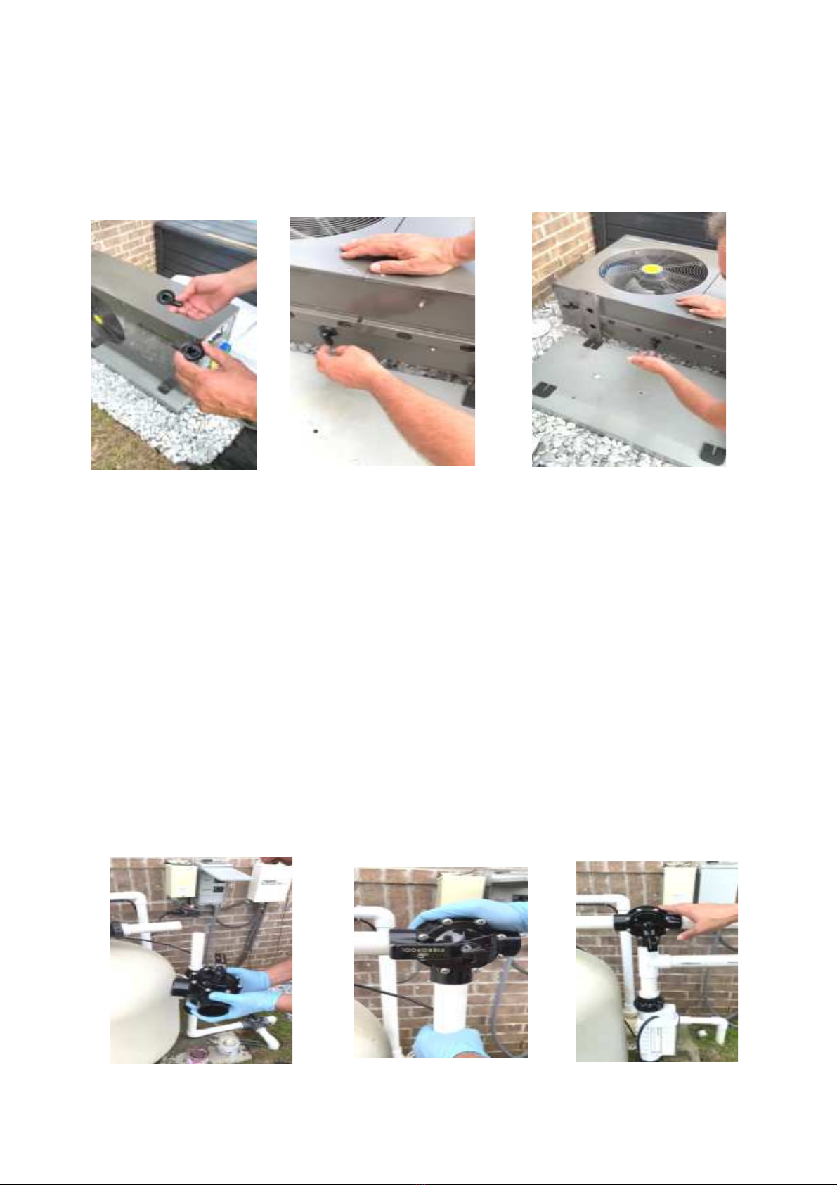
DRAIN ADAPTERS
Please install the darin adapters beneath the heater prior to installation You can add 5/8 hose to
the adapters to direct the condensation water
PLUMBING
·A typical installation on a pool with a small pump, such as ½, ¾ hp pump with 1 1/2” pvc or
flexible pipes, just requires pipes to go in from the bottom and exit thru top
·For stronger systems, with 1 0 Hp and larger pumps, and 2 inch plumbing systems, a bypass
system should be installed
·If The heat pump is connected to a filtration circuit with a by-pass valve; The bypass valve
should be partially opened (throttled), while all the other valves should be completely
opened We suggest to open bypass 50% then adjust until the lowest volume of water going
through the heater, but no error messages ( EE-3, PL, EE1) are present This will give
enough water to the heater, and not restrict your flow
·The old system BYPASS path usually consists of 3 valves The New FIBROPOOL BY PASS
VALVE is just 1 valve That makes it possible to adjust water flow which passes through heat
pump
V-2105 Fibropool Co LLC, Ms USA

1. Installation of a Single Heater
2. Parallel Installation for 2 Units
Throttled by pas valve, 50% open
V-2105 Fibropool Co LLC, Ms USA

PIPE C NNECTI NS
1. FH 270 Features 1 1/2” SAE machine threads They are NOT the typical pipe threads You
can use the included unionized fittings with o rings, WITHOUT thread tape, or you can use
the conical hose adapters, WITH thread tape
2. All fittings and pipes used must be 1 1/2” Sch 40 ( Schedule 40) PVC pipe
3. Tighten all fittings by hand only If using the threaded hose adapters, give a ¼ turn with
pliers after hand tight Excessive tightening will crack fittings
4. A minimum of 6 inches of straight pipe must be used before any elbows/ fittings etc
5. Please support the pipes in the air, as gravity will eventually bend and break the fittings
6. If using flexible hoses, be sure to tighten the clamps well
7. Be sure to check your fittings and glue them properly, using pipe cleaner and a good grade
Medium bodied glue
8. Heaters have heat exchanger coils, therefore they increase back pressure
9. If your pool pump is larger than 1 horsepower, you should use a bypass valve This will help
water flow of your system to continueas original plumbing You simply need to get a 3 way
valve, and a Tee Refer to diagrams for the bypass set up
10. If you have 2 inch plumbing, use our 2 inch bypass valve and a 2 inch TEE, then use
reducers to 1 1/2” pipe to connect to the heater This way you will not compromise the water
flow
11. Be sure that WATER IN pipe is connected to the bottom, and WATER OUT pipe is on Top
Reversal will result in flow error codes
V-2105 Fibropool Co LLC, Ms USA

ELECTRICAL C NNECTI NS
Pow r Supply Wir s Siz
Mod l Pow r Supply Wir s
Power Supply Cable Diameter Specification
Fh 270 208-240V/60Hz 3×4 0mm (3×0 157inch) AWG 12
WARNING: Pow r supply of h at pump must b disconn ct d b for any op ration.
➢St p 1: D tach front pan l by a scr wdriv r.
➢St p 2: Ins rt cabl into h at pump l ctrical conn ctor port. This port is d sign d for
outdoor SO cords (wat rproof fl xibl cords.) If using a fl xibl conduit, simply r mov
th adapt r, and install conduit adapt r.
➢St p 3: Conn ct pow r supply cabl to t rminal block according to th diagram b low.
➢FH 270 do s NOT hav a NEUTRAL conn ction Th r for , Do NOT us a GFCI br ak r.
➢FH 270 r quir s quipot ntial bonding. Pl as conn ct an #8 AWG bar copp r wir to a
ground rod. This is r quir d for saf ty and corrosion pr v ntion of th h at rs m tal
chassis.
V-2105 Fibropool Co LLC, Ms USA
Table of contents
Other FibroPool Heat Pump manuals


Popular Heat Pump manuals by other brands


Mitsubishi Electric
Mitsubishi Electric PUZ-SWM60VAA Service manual

Dimplex
Dimplex LI 16I-TUR Installation and operating instruction

Carrier
Carrier WSHP Open v3 Integration guide

TGM
TGM CTV14CN018A Technical manual

Carrier
Carrier 38MGQ Series installation instructions

Kokido
Kokido K2O K880BX/EU Owner's manual & installation guide

Viessmann
Viessmann VITOCAL 300-G PRO Type BW 2150 Installation and service instructions

Carrier
Carrier 48EZN installation instructions

Viessmann
Viessmann KWT Vitocal 350-G Pro Series Installation and service instructions for contractors

Ariston
Ariston NIMBUS user manual

Weishaupt
Weishaupt WWP L 7 Installation and operating instruction

GE
GE Zoneline AZ85H09EAC datasheet