Fenice Power PX Series User manual
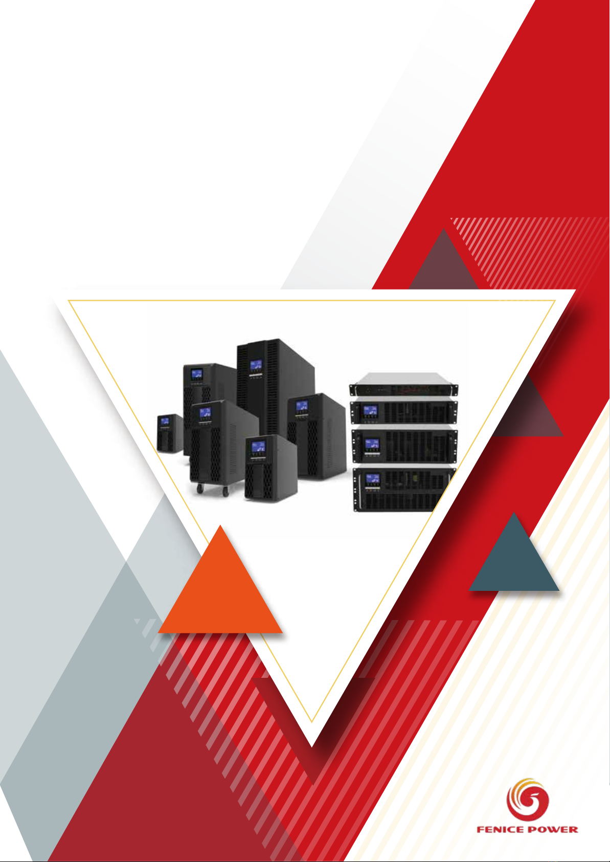
USER
MANUAL
PX1~20K Online UPS

2
Introduction
Thanks for choosing PX Series UPS products!
PX Series double conversion online UPS powered by DSP digital control technology and
high frequency PWM Inverter technology, output clean and stable AC mains supply, provides
comprehensive protection to mission critical equipment, such as computer, communication
equipment, medical equipment etc. from loss of data or even hardware damage by power
blackout or other kind of power quality issues.
This manual introduce PX Series UPS functions and features, guidance to installation
operation, maintenance and transportation information.
Please read this manual carefully and thoroughly before operation the UPS. The manual is
offered when you purchase our product.

3
Content
Chapter 1 Safety Instruction.......................................................................................................................................4
Chapter 2 Product Introduction..................................................................................................................................5
2.1 Product introduction...................................................................................................................................... 5
2.2 Product Model List.........................................................................................................................................5
2.3 UPS Outlook...................................................................................................................................................6
Chapter 3 Installation.................................................................................................................................................11
3.1 Product inspection....................................................................................................................................... 11
3.2 Installation.....................................................................................................................................................11
3.3 Wiring ............................................................................................................................................................11
Chapter 4 Panel & Operation Guide....................................................................................................................... 19
4.1 Front panel................................................................................................................................................... 19
4.2 UPS Working Mode.................................................................................................................................... 21
4.3 Operation...................................................................................................................................................... 22
Chapter 5 Maintenance.............................................................................................................................................24
5.1 Routine Maintain ........................................................................................................................................ 24
5.2 Battery Maintain...........................................................................................................................................24
Chapter 6 Trouble shooting...................................................................................................................................... 25
6.1 LCD Warning and Fault Code................................................................................................................... 25
Chapter 7 Specification.............................................................................................................................................26
7.1 1 phase input model Specification........................................................................................................... 26
7.2 3phases input model Specification...........................................................................................................27
7.2 Mechanical................................................................................................................................................... 28
7.3 Environmental.............................................................................................................................................. 28
7.4 EMC & Safety Regulation.......................................................................................................................... 29
Warranty...................................................................................................................................................................... 29

4
Chapter 1 Safety Instruction
This manual contains important instructions that you should follow during installation and maintenance of the
UPS and batteries. Please read all instructions before operating the equipment and save this manual for
future reference.
Strictly follow the Safety instruction for equipment installation, operation and maintenance, inappropriate
operation may cause injury to personnel and equipment. Manufacturer assume no responsibility for violation
of operation.
Danger
This UPS contains LETHAL VOLTAGES. All repairs and service should be performed by AUTHORIZED
SERVICE PERSONNEL ONLY. There are NO USER SERVICEABLE PARTS inside the UPS.
CUT OFF all power supply before any installation and manipulation of power wiring.
Reverse connection polarity, short-circuit of battery terminal may cause harmful high current, or even fire,
make sure proper connect battery.
Cable with sufficient current rating should be used for wiring, secure fixation and proper insulation are all
required to avoid fire accident cause by wired overheat or short-circuit.
Warning
This UPS contains its own energy source (batteries). The UPS output may carry live voltage even when
the UPS is not connected to an AC supply.
To reduce the risk of fire or electric shock, install this UPS in a temperature and humidity controlled,
indoor environment, free of conductive contaminants. Ambient temperature must not exceed 40°C
(104°F). Do not operate near water or excessive humidity (90% maximum).
To reduce the risk of fire, connect only to a circuit provided with branch circuit over-current protection .
Output over current protection and disconnect switch must be provided by others.
To comply with international standards and wiring regulations, the sum of the leakage current of the UPS
and the total equipment connected to the output of this UPS must not have an earth leakage current
greater than 3.5 milliamperes.
If installing optional rack-mount Battery Pack, install the Battery Pack directly below the UPS so that all
wiring between the cabinets is installed behind the front covers and is inaccessible to users.
Caution
Batteries can present a risk of electrical shock or burn from high short-circuit current. Observe proper
precautions. Servicing should be performed by qualified service personnel knowledge of batteries and
required precautions. Keep unauthorized personnel away from batteries.
Proper disposal of batteries is required. Refer to your local codes for disposal requirements.
Never dispose of batteries in a fire. Batteries may explode when exposed to flame.
In the event of fire occurring in the vicinity, please use dry powder fire extinguishers. The use of liquid
fire extinguishing agents may cause electric shock.

5
Chapter 2 Product Introduction
2.1 Product introduction
PX Series single phase Uninterruptible Power Supply (UPS) is a new generation product
incorporating advance digital control technology and double-conversion power topology, the
product capable of working with ultra wide range of electric input with high efficiency and
reliability, protect mission critical equipment with clean, safe, high-quality AC power supply. The
PX Series UPS user friendly interface make it easy to use, the small dimension for saving
valuable installation space, perfectly meet infrastructure needs in areas of IT, finance, traffic
control, manufacturing industry, education and government etc.
2.2 Product Model List
PX Series UPS model naming rule shown below.
PX [n] K [R] [L]
n indicates capacity of UPS1,2,3,6,10,15,20kVA product for this manual.
[R] With R indicates Rack mounted model, without R is Tower form factor.
[L] With L indicates Long Backup Time model, UPS can connect with external batteries
for extra long backup time. And product model name without L indicates standard backup time
model with internal battery.
Product type and Capacity
Model Name Remark
Standard
Model
1KVA
PXIK(R)
With a 1A internal charger and 2 Pcs batteries
2KVA
PX2K(R)
With a 1A internal charger and 4 Pcs batteries
3KVA
PX3K(R)
With a 1A internal charger and 4 or 6 Pcs batteries
6KVA
PX6K(R)
With a 1A internal charger and 16 batteries
10KVA
PX10K(R)
With a 1A internal charger and 16 batteries
15KVA PX15K(R)-3P1 With a 1A internal charger and 32 batteries
20KVA
PX20K(R)-3P1
With a 1A internal charger and 32 batteries
Long Backup Time
Model
1KVA
PX1K(R)L
With a 4A internal charger and external battery
2KVA
PX2K(R)L
With a 4A internal charger and external battery
3KVA
PX3K(R)L
With a 4A internal charger and external battery
6KVA
PX6K(R)L
With a 4A internal charger and external battery
10KVA
PX10K(R)L
With a 4A internal charger and external battery
15KVA
PX10K(R)L-3P1
With a 4A internal charger and external battery
15KVA
PX15K(R)L-3P1
With a 4A internal charger and external battery
20KVA PX20K(R)L-3P1 With a 4A internal charger and external battery
Note: For Rack Mount Product, there are models with or without internal battery, confirm on the
product name plate or consult with distributor for best suitable to your application.

ON/OFF FUNC

Circuit
Breaker
AC
INPUT
AC
OUTPUT
RS232 LAN Port
(Option)
Circuit
Breaker
RS232
Output
Socket
AC
Input
LAN
(Option)
RS232
LAN
Option
External
Battery
Output
Socket
AC
INPUT
Circuit
Brearker
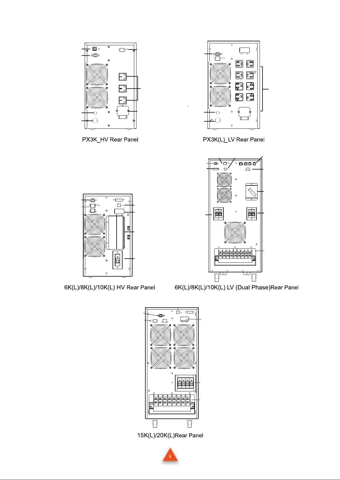
Circuit
Breaker
AC
Input
Output
Socket
RS232
Output
Terminal
USB Port
(Option) LAN
(Option)
Output
Socket
Input
Breaker
AC Input
RS232
External
Battery
Connector
Input
Circuit
Breaker
RS232 USB
(Option)
LAN
(Option)
Input /
Output
Terminal
block
Input/Output
Terminal block
AC
Input
Breaker
Output
breaker
Maintenance
Bypass
Switch
(Option)
RS232
EPO
(option)
LAN
(Option)
MODBUS
(option)
USB
(Option) RJ45&RJ11
SPD
(Option)
AC Input &
Output Terminal
Block
AC input
Circuit
Breaker
RS232
LAN Port
MODBUS
(Option)
External
Battery
Connector

Input/Output Terminal
L N G L
N
AC INPUT AC OUTPUT
AC OUTPUT
RS232
RS232 Output Socket
L N G L
N
AC INPUT AC OUTPUT RS232 BAT+ BAT-
I/P CB
Input/Output Terminal RS232
External Battery Terminal
RS232
External Battery
connector
Output Terminal Block
Input Circuit Breaker
AC Input Output socket
LAN(Option)
RS232
External Battery
connector
Output Terminal Block
Input Circuit Breaker
AC Input Output socketLAN(Option)
RS232
External Battery Connector
AC Input Breaker
AC Input / Output Terminals USB (option)
LAN (option)

10
Note:
1. The socket and terminal configuration on the rear panel may be slightly different for countries or
regions according to order.
2. External battery connectors available only for long backup type UPS.
AC Input Circuit Breaker
AC Input/ Output Terminal Block
External Battery Connector
Ethernet Card
(Option) RS232 USB(Option)
AC Input & Output Terminal Block External Battery
Connector
Mains Input Circuit Breaker RS232
Port
Ethernet Card
(Option)
This manual suits for next models
30
Table of contents
Other Fenice Power UPS manuals