Faulhaber Series BLD 3502 User manual
BLD 3502
Series
Operating Instructions
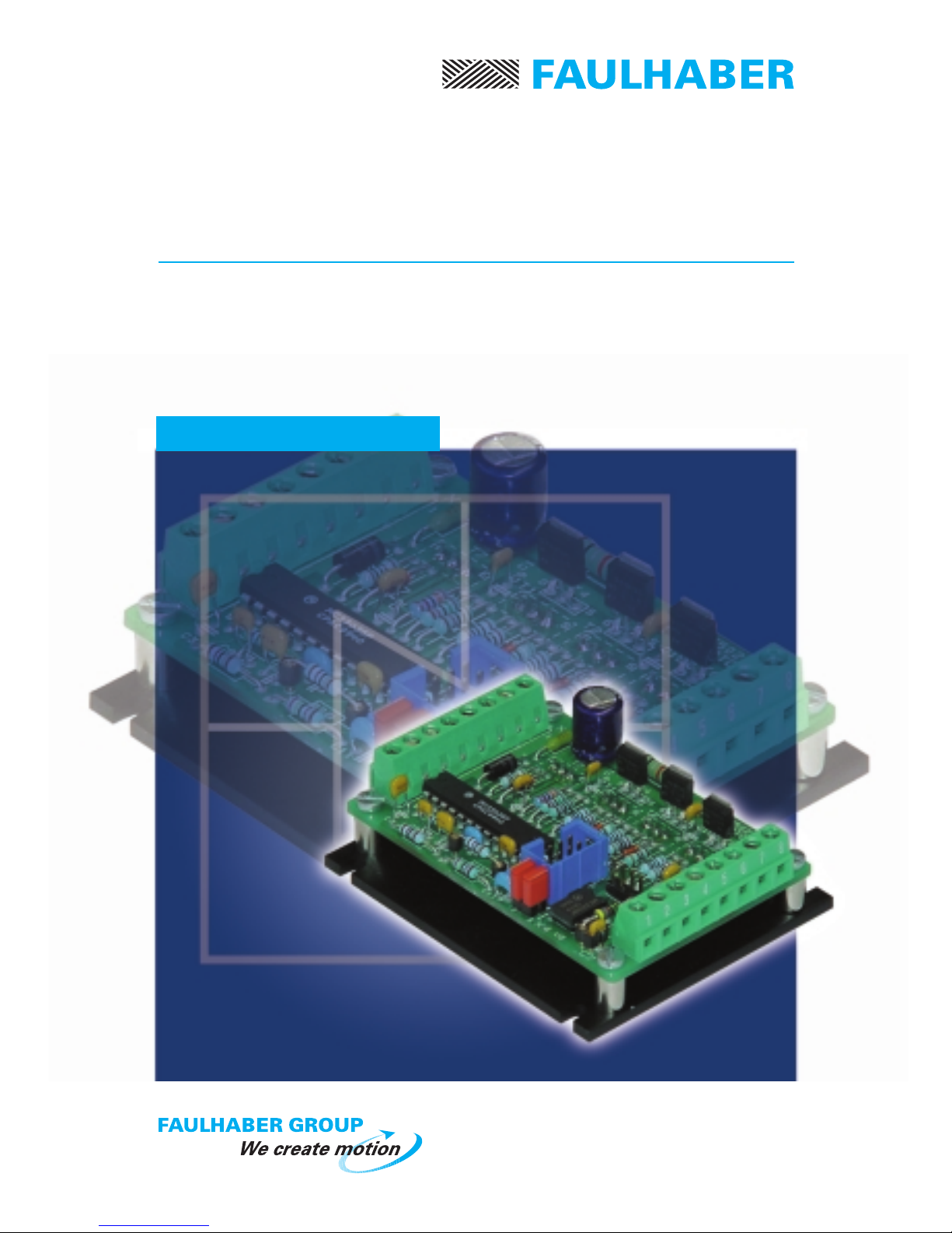
Servo Amplifier
2-Quadrant PWM for Brushless DC-Servomotors

http://www.minimotor.ch/minicatalog/pdf/DriveCircuits/Manuals/IM_BLD_3502.pdf
www.minimotor.ch/uk/pr/
For direct Download:
w
w
w
.
f
a
u
l
h
a
b
e
r
.
c
o
m
Miniature Drive Systems
Micro Drives
DC-Micromotors
Precision Gearheads
Servo Components
Drive Electronics
Surf to the following Internet
address and you will find the
latest edition of the instruction
manual on-line :

1
Index
1. Description
2. Illustration
General information
3. Maximum ratings
4. Specific characteristics
5. Dimensions and weight
6.1 Analog Speed command
6.2 Direction
6.3 Enable
6.4 Brake
6.5 Power supply internal fuse
6.6 Encoder feedback
6.7 Basic block diagram for speed control with Hall sensor feedback
6.8 Basic block diagram for speed control with encoder feedback
8.1 Power supply
8.2 Wiring
Notice of use
Start-up procedure
7.1 Brushless DC-Servomotor with Hall sensors feedback (standard)
7.2 Connection diagram
7.3 Brushless DC-Servomotor with encoder feedback (optional)
7.4 Connection diagram
7.5 Brushless DC-Servomotor with encoder IE2 – 512
7.6 Connection diagram
7.7 Speed range selection with Hall sensors feedback
7.8 Speed range selection with encoder feedback
General characteristics
Technical data

1.
2
2.
General information
Description
Illustration
Figure 1
Specifications subject to change without notice
Connector X2
to connect power supply and
command signal wires
Connector X3
to connect the
optional encoder.
Heat sink with four
mounting slots Ø 3,2 mm
Fuse F1
security for the power supply
input
The BLD 3502-SE2P is a 2-Quadrant PWM (Pulse-Width Modulation) Servo Amplifier suitable
for speed control of our three-phase brushless DC-Servomotors, type 1628, 2036 and 2444.
The phase commutation sequence of the brushless DC-Servomotor is automatically made by
the Servo Amplifier.
A specially designed frequency-to-voltage converter allows precise speed regulation
(regulator type P, proportional).
Two amplifier configurations for speed control:
• Hall sensors signals for operation above 1000 rpm;
• Encoder signals for operation down to 100 rpm.
The Servo Amplifier is supplied with Hall sensor configuration as standard.
The analog speed command is a unipolar signal, from 0 to +5 V, (optional 0 to +10 V)
producing a fixed speed proportional to the input voltage.
The maximum output power without additional heat sink is 50 W.
Resistance R20
for optional 0 to 10 V ASC
Resistance R13
modifies the gain
Capacitor C7
modifies the gain
Connector X5
used with encoder
IE2 – 512
Connector X1
to connect the
brushless DC-Servo-
motor wires
Connector X4
when used with encoder
both jumpers must be removed
3
5.
3502-SE2P
77
6,4
65
1 2 3 4 5 6 7 8
3
26
X1
X2
1
1
8
8
3,2
64
±1
C1
F1
R13
R20
X3
X4
1
4
C7
X5
12
56
3.
4.
Specifications subject to change without notice
Technical data
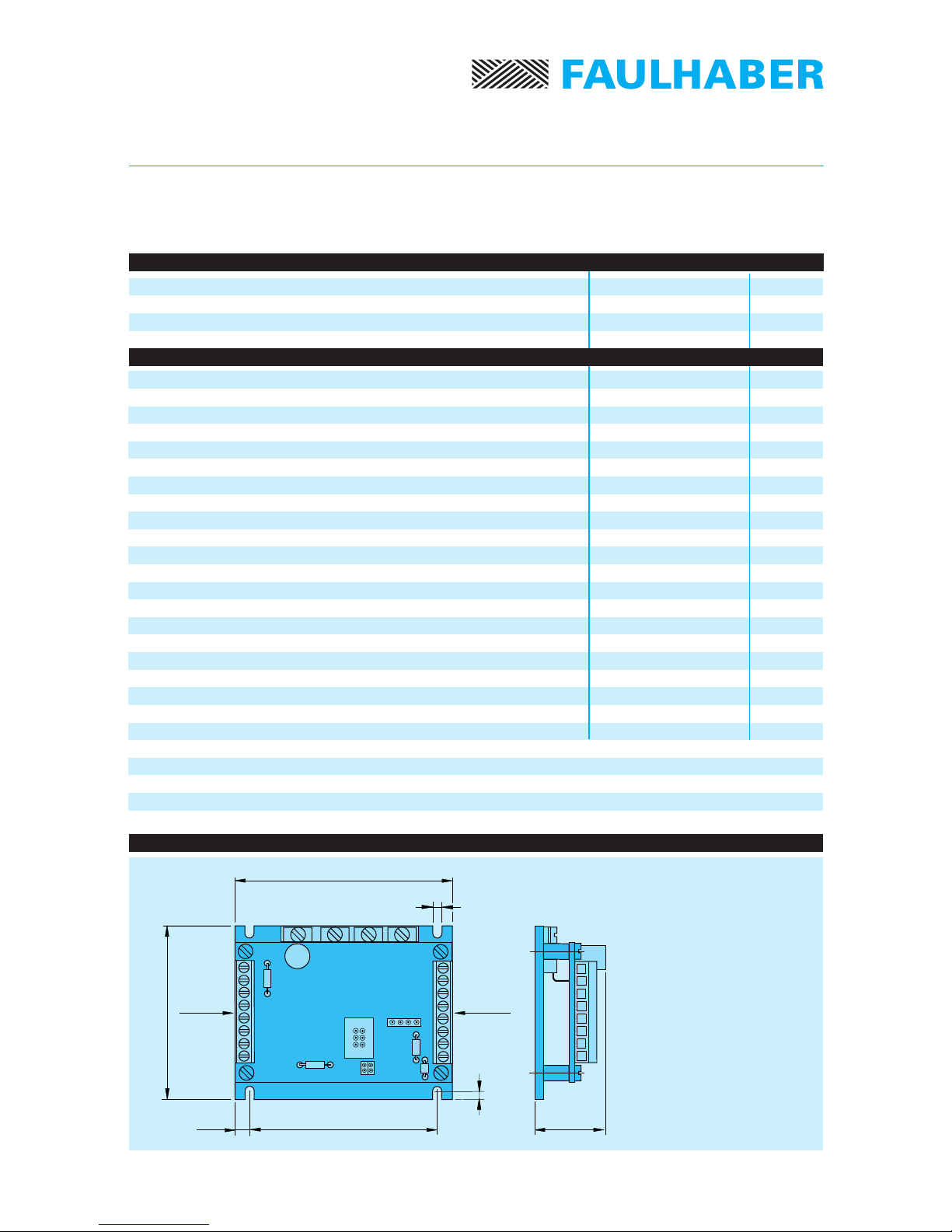
Dimensions and weight
Figure 2
Dimensions
length 77 mm
width 65 mm
height 26 mm
Weight 100 g
Scale reduced
1) Analog speed command may be set by an external potentiometer or an external voltage.
2) The maximum controllable speed depends on the gain of the Servo Amplifier,
the power supply, the motor type and the load.
3) The minimum controllable speed depends on the motor type and the load.
Power Stage:
– Power supply
– Total output voltage drop (Imotor =2A)
Switching frequency
Current limit (pulse-by-pulse current limiting)
Analog speed command: 1)
– Voltage range
– Input resistance
– Frequency bandwidth
Logic inputs
Output voltage for external use (max. load 50 mA)
Total standby current without encoder
(Hall sensors supply included)
Maximum controllable speed with Hall sensor 2)
Minimum controllable speed with Hall sensor 3)
Minimum controllable speed with encoder 3)
Temperature range:
– Operating temperature
– Storage temperature
Power supply
Logic and analog inputs
Continuous output current @ TA= 22°C
Maximum ratings
Specific characteristics
35 V DC
-0,3 to +10 V DC
1,5 A
12 ÷35 V DC
3,8 V DC
25 kHz
3A
0 ÷5VDC
36 kΩ
117 Hz
TTL
5,5 V DC
55 mA
60 000 rpm
1 000 rpm
100 rpm
0 ... + 70 °C
–20 ... + 80 °C

4Specifications subject to change without notice
General characteristics
6. General characteristics
6.1 Analog Speed command
The speed command is given by an external voltage from 0 to +5 V (optional 0 to +10 V)
or by a potentiometer connected directly to the Servo Amplifier (see fig. 5). The total
potentiometer resistance must be between 10 kΩand 47 kΩ.
Furthermore, a PWM signal with a maximum amplitude of 5 V and a minimum frequency of
1 kHz, can be used as speed command.
To control the Servo Amplifier using an analogue speed command voltage
from 0 to +10 V, it is necessary to change the R20 resistance value from 18 kΩ(standard) to
5,6 kΩ.
6.2 Direction
The direction of rotation is reversed using either a logic high or low input signal.
If not connected (internal pull-up resistance) or a high input signal is applied,
the motor runs in CW direction.
If a low input signal is applied, the motor runs in CCW direction.
6.3 Enable
A high logic at this input causes the motor run.
If not connected (internal pull-up resistance) the Servo Amplifier is enabled.
6.4 Brake
A logic low state (connect to GND) at this input allows the motor to run.
6.5 Power supply internal fuse
An internal F1 fuse is provided on the print board to protect the Servo Amplifier against:
- power supply polarity inversion
- over-load (over-current).
Fuse specification:
2A / 125V - subminiature fuse / Littelfuse type 251.002HE
6.6 Encoder feedback
The option with encoder allows the two incremental encoder channels to be used to
control the motor speed down to 100 rpm.
To use this speed control configuration it is necessary to remove the two jumpers on X4.
Refer to the start-up procedure point 7.3.

5
A
B
C
A
B
C
*
+–
+5,5V
GND
A
B
C
A
B
C
*
+–
+5,5V
A
B
GND
* Current limiting
GNDVm
Speed
amplifier BLM
Driver
F/V
converter
Phase
Phase
Phase
Hall sensor
Hall sensor
Hall sensor
Brushless
DC-Servomotor
1628 ... B
2036 ... B
2444 ... B
Logic
Analog speed
command
Direction
(CW/CCW)
Brake
Enable
6.7 Basic block diagram for speed control with Hall sensor feedback
6.8 Basic block diagram for speed control with encoder feedback
* Current limiting
GND
Vm
Speed
amplifier BLM
Driver
F/V
converter
Phase
Phase
Phase
Hall sensor
Hall sensor
Hall sensor
Logic
Analog speed
command
Direction
(CW/CCW)
Brake
Enable
Channel
Channel
Encoder
General characteristics
Figure 4
Figure 3
Specifications subject to change without notice
Brushless
DC-Servomotor
1628 ... B
2036 ... B
2444 ... B

6Specifications subject to change without notice
Start-up procedure
7.2 Connection diagram
7.1 Brushless DC-Servomotor with Hall sensor feedback (standard)
7.
Start-up procedure
References
7.2 Connection diagram
7.5 Speed range selection
8
7
6
5
4
3
2
1
1
2
3
4
5
6
7
8
X2
X1
Phase C
Phase B
Phase A
GND Logic
+ V CC
Hall sensor C
Hall sensor B
Hall sensor A
Yellow
Orange
Brown
Black
Red
Grey
Blue
Green
GND
Vm power supply
GND Logic
Analog speed comm.
+ V CC
Enable
Brake
Direction (CW)
Figure 5
Important: Before connecting it is recommended to read chapter 8.
Procedure
- Connect the Servo Amplifier
- Connect Brake Pin 7 with GND Logic Pin 3
- Select R13 resistance
- Power the Servo Amplifier
- Verify the operation
Brushless
DC-Servomotor
1628 ... B
2036 ... B
2444 ... B

7
Servoamplificatore BLD 3502-SH2P
Start-up procedure
References
7.4 Connection diagram
7.6 Speed range selection
7.3 Brushless DC-Servomotor with encoder feedback (optional)
7.4 Connection diagram
Important: Before connecting it is recommended to read chapter 8.
8
7
6
5
4
3
2
1
1
2
3
4
5
6
7
8
X2
X1
1
2
3
4
X3
X4
+ V CC
Channel A
Channel B
GND
Note:
For encoder,
jumpers on X4 must
be removed.
Phase C
Phase B
Phase A
GND Logic
+ V CC
Hall sensor C
Hall sensor B
Hall sensor A
Yellow
Orange
Brown
Black
Red
Grey
Blue
Green
GND
Vm power supply
GND Logic
Analog speed comm.
+ V CC
Enable
Brake
Direction (CW)
Encoder
Figure 6
Procedure
- Connect the Servo Amplifier
- Connect Brake Pin 7 with GND Logic Pin 3
- Connect the encoder
- remove the two jumpers on X4
- Select R13 resistance and C7 capacitor
- Power the Servo Amplifier
- Verify the operation
Specifications subject to change without notice
Brushless
DC-Servomotor
1628 ... B
2036 ... B
2444 ... B

8
References
7.4 Connection diagram
7.6 Speed range selection
7.5 Brushless DC-Servomotor with encoder IE2 – 512
7.6 Connection diagram
Important: Before connecting it is recommended to read chapter 8.
8
7
6
5
4
3
2
1
1
2
3
4
5
6
7
8
X2 X1
1
2
3
4
5
6
X5
X4
–
–
GND
+ V CC
Channel A
Channel B
Note:
For encoder,
jumpers on X4 must
be removed.
Phase C
Phase B
Phase A
GND Logic
+ V CC
Hall sensor C
Hall sensor B
Hall sensor A
Yellow
Orange
Brown
Black
Red
Grey
Blue
Green
GND
Vm power supply
GND Logic
Analog speed comm.
+ V CC
Enable
Brake
Direction (CW)
Encoder
IE2 – 512
Figure 7
Procedure
- Connect the Servo Amplifier
- Connect Brake Pin 7 with GND Logic Pin 3
- Connect the encoder
- remove the two jumpers on X4
- Select R13 resistance and C7 capacitor
- Power the Servo Amplifier
- Verify the operation
Specifications subject to change without notice
Brushless
DC-Servomotor
1628 ... B
2036 ... B
2444 ... B
Start-up procedure
Table of contents
Other Faulhaber Amplifier manuals


