Fasep VIDEOTRONIC V688.G3 User manual

Fasep 2000 srl Rev. 1.0
Videotronic V688.G3: User’s Manual 15 July 2019
For any information, please contact: www.fasep.it
e-mail: [email protected]
FASEP 2000 srl
Via Faentina 96
50032 Ronta (Fi) Italy
Tel. #39 055 840 3126
Fax #39 055 2691906 i
VIDEOTRONIC V688.G3
USER’S MANUAL

Fasep 2000 srl Rev. 1.0
Videotronic V688.G3: User’s Manual 15 July 2019
ii
WARNING
.This document contains information which is the property of FASEP 2000 rl and all rights are reserved. This manual shall not be
photocopied or reproduced in any way without the prior written consent of FASEP 2000 srl.
.FASEP 2000 srl reserves the right to revise products firmware, software or documentation without obligation to notify any person
or organization. The information contained in this document is subject to change without warning.
.Prior of the installation of the unit described in this manual, user should read this manual carefully to be instructed properly on
installation, use and maintenance of the unit.
.Failing to read this manual and operate accordingly may cause damage to the user or the unit.
.FASEP 2000 srl shall not be responsible for inconvenience, breakdown, accidents due to uncomplete knowledge of this manual
or uncomplete application of raccomendations described in this manual.
.FASP2000srlshallnotberesponsibleforinconvenience, breakdown, accidentsduetounauthorizedmodifications of the unit, use
ofnon-original or unauthorizedaccessories(see Accessories listingin this manual for alist oforiginal accessories available forthis
model).
.FASEP2000 srl shall not beresponsible for any inconvenience,breakdown, accidents caused directlyor indirectlyby not
qualified service. Service to any parts by not qualified persons will void warranty and will void any right of the owner of
the unit.
SYMBOLS AND CONVENTIONS
To speed the retrieval of main information and make easy to understand the instructions, this manual uses the following typing
conventions:
<NAME OF THE PUSH BUTTON> Used to indicate name of push-buttons on the control panel.
DISPLAY Used to indicate text or number visible on the displays on the control panel.
ADVICES Contain useful advices or solutions, evidence d with respect to the rest of the text.
NOTE Notes contain important information, evidenced to the rest of the text.
WARNING Warning messages appears corresponding to procedures that, if not properly observed,
may lead to loose of data or cause damage to the unit.
!CAUTION Caution messages appears corresponding to procedures that, if not properly observed,
may cause injuries to the user.

Fasep 2000 srl Rev. 1.0
Videotronic V688.G3: User’s Manual 15 July 2019
iii
ORIGINAL INSTRUCTIONS
TABLE OF CONTENTS
WARNING .......................................................................................... ii
SYMBOLSANDCONVENTIONS ........................................................................ ii
1 PRESENTATION ............................................................................1-1
1.0 Intended Use .......................................................................1-1
1.1 Definitions .........................................................................1-1
2 INSTALLATION .............................................................................2-1
2.1 Movingtheunit......................................................................2-1
2.2 Assemblingtheunit ..................................................................2-1
2.3 Installation .........................................................................2-1
2.4 ElectricalHookup....................................................................2-1
2.5 Compressed air Hookup (PL models only) ................................................2-1
2.6 Power.............................................................................2-1
3 USEOFCONTROLPANEL....................................................................2-2
3.1 Meaning of the icons on the screen ......................................................2-2
4.0 CALIBRATIONOFWHEELBALANCER..........................................................2-5
4.1 How to calibrate the wheel balancer .....................................................2-5
4.2 How to control the calibration of wheel balancer and position weight ............................2-6
5 CalibrationALU-SE ..........................................................................3-5
6 CalibrationSME .............................................................................3-6
7 MEASUREMENTANDCORRECTIONOFUMBALANCE ............................................3-7
7.1 Placing the wheel rim on the wheel balancer ...............................................3-7
7.2 Input of Rim Dimensions (external measuring system version) .................................3-7
7.3 Input of Rim Dimensions (ALU-SE or LASER version) .......................................3-8
7.4 Detecting and correcting umbalance .....................................................3-8
7.5 How to apply the weight using ALU-SE applicator ...........................................3-9
7.6 How to apply the weight using LASER ....................................................3-9
7.7 HowtouseSPLITProgram ............................................................3-9
8 HOWTOOPTIMIZEUNBALANCEOFTHEWHEEL ................................................4-1
9 SPECIAL FUNCTIONS .......................................................................5-1
9.1 Language selection ..................................................................5-1
9.2 Setup .............................................................................5-1
APPENDIX ........................................................................................ A-2
A: Technicaldata ..................................................................... A-2
B: Environmental Data, Safety Features and Requirements .................................... B-1
C: Errors and Malfunctions recognized by the Computer ....................................... B-2
D: How to remove the battery from the product safely. ........................................ B-3

Fasep 2000 srl Rev. 1.0
Videotronic V688.G3: User’s Manual 15 July 2019
1-1
1 PRESENTATION
1.0 Intended Use
This unit is designed to measure and correct static and dynamic unbalance of vehicle wheel, the dimension and weight
of which are within the working range of the machine (see “Technical Data”appendix for reference)
This unit is meant for a professional use. Operator shall be properly trained before use. Training Course is not included
in the price of the unit and must be purchased separately.
This unit is designed for indoor use only (see “Environmental Data”appendix for reference).
!CAUTION: This unit is designed to spin vehicle wheels only, within the range of dimensions and weight
approved (see “Technical Data”appendix for reference). Special adaptors suit this purpose. Do not
attempt to use the machine to spin anything else. Unproper locking may cause the part being
spinned to be ejected, causing damage to the unit itself, the operator or anything in the in the
neighboorhood.
1.1 Definitions
1. Monitor
2. Back-mounted weight-compartments
3. Weights and tools trays
4. Side flange-holders
5. Wheel guard
6. UL 3D Automatic Input Sonar
7. Quick lock + HD shaft
8. 3dWall
9. Foot-pedal

Fasep 2000 srl Rev. 1.0
Videotronic V688.G3: User’s Manual 15 July 2019
2-1
2 INSTALLATION
2.1 Moving the unit
WARNING When the unit has to be moved: never lift
balancerbymotorshaft or byneighborhoodofit.
2.2 Assembling the unit
Foreaseoftransportation,thewheelbalancermightbedisassembled
into units. If necessary, assembling instruction are provided within
each package..
2.3 Installation
The wheel balancer must be installed on a firm and level ground.
NOTE:the machine must be secured to the floor. Using four holes
in the base and anchor bolts provided
2.4 Electrical Hookup
!CAUTION: Failure to follow these instructions can results in
damage to unit or create an electrical hazard and
will void warranty..
2.4.1 Electrical hookup is to be provided by a qualified electrician.
2.4.2 A fusible wall-mounted switchbox is required at the installation site. This
switch should provide on-off control and overload protection for your
wheel balancer only. The switchbox should be fused with time-delay
fuse(s) in accordance with the power rating specified on your wheel balancer.
2.4.3 Electrical connection of the machine should be by plug connectors.
2.4.4 The balancer must be effectively connected to ground. The electric cord is regularly provided with a ground terminal.
2.4.5 Make sure that Power Rate Specifications for your wheel balancer (refer to nameplate on the wheel balancer) comply
with those provided by the external power source.
!CAUTION Afterelectricalhookuphasbeenperformedunitisreadytooperate.Always observepertinentsafety
precautions when operating the unit (see Appendix tables for an overview of relevant Safety
requirement).
2.5 Compressed air Hookup (PL models only)
!CAUTION Failure to follow these instructions can result in damage to unit or create a hazard and will void
warranty.
1. Compressed Air hookup is to be provided by a qualified technician, under the local safety
requirements, in line with relevant national standards and regulations. All fitting and hoses must
conform to local codes.
2. A wall-mounted lubricator and water-separator is required at the installation site.
3. Compressed Air circuit to the balancer shall be regulated to a maximum pressure of 7 atm.
Overpressure could compromise cylinder operation.
2.5.1 CONNECT TO AIR SUPPLY:
The machine is fitted with a universal connector and therefore no other special or additional fitting is required. Push all
the way onto the connector a high pressure rubber air-hose and secure it.
2.6 Power
Plug the wheel balancer into a 220V socket. To switch on the wheel
balancer press the red button (power) until it light up. To switch off the
wheel balancer press the red button (power) until it light off.
Fasep 2000 srl Rev. 1.0
Videotronic V688.G3: User’s Manual 15 July 2019
2-2
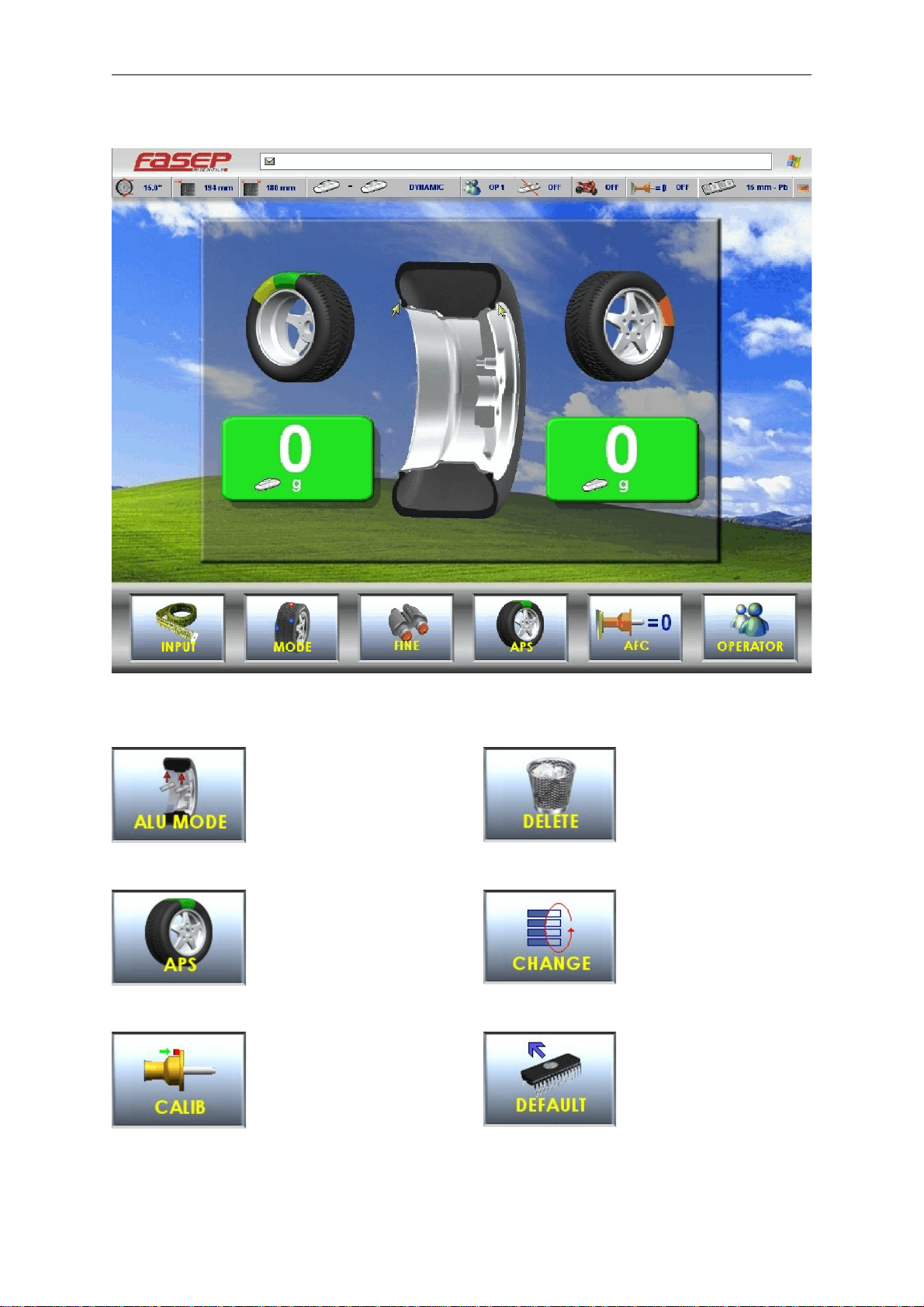
3 USE OF CONTROL PANEL
3.1 Meaning of the icons on the screen
Select balancing
mode
APS Function
Calibration
Delete last character in input
activation code
Change selection
Set default values
Fig. 6 Panel V643
Fig. 7
Fig. 8
Fig. 9
Fig. 10
Fig. 11
Fig. 12

Fasep 2000 srl Rev. 1.0
Videotronic V688.G3: User’s Manual 15 July 2019
2-3
Diagnostic
Key down
Position calibration
Go to previous page
Fine resolution
Access to Information center
Access to page measures
Laser calibration
Put in the rod laser in rest
position
Start laser
Extract fully rod laser
Manul input measures
Set Dynamic/Static
Mode moto
Fig. 13
Fig. 14
Fig. 15
Fig. 16
Fig. 17
Fig. 18
Fig. 19
Fig. 20
Fig. 21
Fig. 22
Fig. 23
Fig. 24
Fig. 25
Fig. 26

Fasep 2000 srl Rev. 1.0
Videotronic V688.G3: User’s Manual 15 July 2019
2-4
Key SET/OK
Double operator
Optimize
Restart software
Reset partial statistics
Reset variation in page Sensor
Save
Set measures
Go to setup menù
Skip current operation
Split function
Stop turning wheel
Key up
View menù and selection
(UP/DOWN)
Automatic flange calibration
Fig. 27
Fig. 28
Fig. 29
Fig. 30
Fig. 31
Fig. 32
Fig. 33
Fig. 34
Fig. 35
Fig. 36
Fig. 37
Fig. 38
Fig. 39
Fig. 40
Fig. 41

Fasep 2000 srl Rev. 1.0
Videotronic V688.G3: User’s Manual 15 July 2019
2-5
Fig. 42
Fig. 43
Fig. 44
Fig. 45
4.0 CALIBRATION OF WHEEL BALANCER
4.1 How to calibrate the wheel balancer (USER)
NOTE:the following symptoms indicate need for calibration::
a) check calibration program fails. b) constant low or high weight readings.
c) indicated point of unbalance constantly wrong d) more than 2 spins required to balance wheels
repeatedly.
Switch on the wheel balancer.
Select SET UP > CALIBRATION > SET/OK >
CALIBRATION > SET/OK.
Spin with no wheel on shaft (Fig. 43)
Close the wheel guard or press <START>.
At the end of the spin, put a wheel (Fig. 44)
and close the wheel guard or press <START>.
At the end of the spin, put the calibration
weight (Fig. 45) and close the wheel guard or
press <START>.
NOTE technical calibration is only available for qualified personnel.

Fasep 2000 srl Rev. 1.0
Videotronic V688.G3: User’s Manual 15 July 2019
2-6
Fig. 46
4.2 How to control the calibration of wheel balancer and position weight (USER)
Switch on the wheel balancer.
Select SET UP > CALIBRATION > SET/OK >
CHECK CALIBRATION > SET/OK.
Put a wheel on the shaft and press <START>
(Fig.47).
Put the calibration weight (Fig.48) and press
<SET/OK>.
Close the wheel guard or press <START>.
At the end of the spin, 160-0 will show on the
video (tolerance allowed is ±10).
Put the weight at 6h o’clock: the weight
indicators of internal side must be both green.
If not, press <6h>.
Put the weight at 6h o’clock and press <SET
OK>.
NOTE technical calibration is only available for qualified personnel.
Fig. 47
Fig. 48
Fig. 49
Table of contents
Other Fasep Wheel Balancer manuals

Fasep
Fasep VIDEOTRONIC V653.G2 User manual

Fasep
Fasep BALATRON B110 User manual

Fasep
Fasep BALATRON B150 User manual

Fasep
Fasep B222 User manual

Fasep
Fasep VIDEOTRONIC V788.G3 User manual

Fasep
Fasep VIDEOTRONIC V644.G3 User manual

Fasep
Fasep RGU 56 XL Operation instructions

Fasep
Fasep B350.G3 User manual

Fasep
Fasep VIDEOTRONIC V548.G4 User manual
Popular Wheel Balancer manuals by other brands


Hofmann
Hofmann geodyna 6900-2p Operation manual

CEMB
CEMB K22 Use and maintenance manual

Hofmann
Hofmann POWER CLAMP features Additional instructions

Desoutter
Desoutter Industrial Tools DU Series user manual

HPA-Faip
HPA-Faip B 235 Evo Operator's manual

Hofmann
Hofmann megaspin 300 Operating instructions manual


