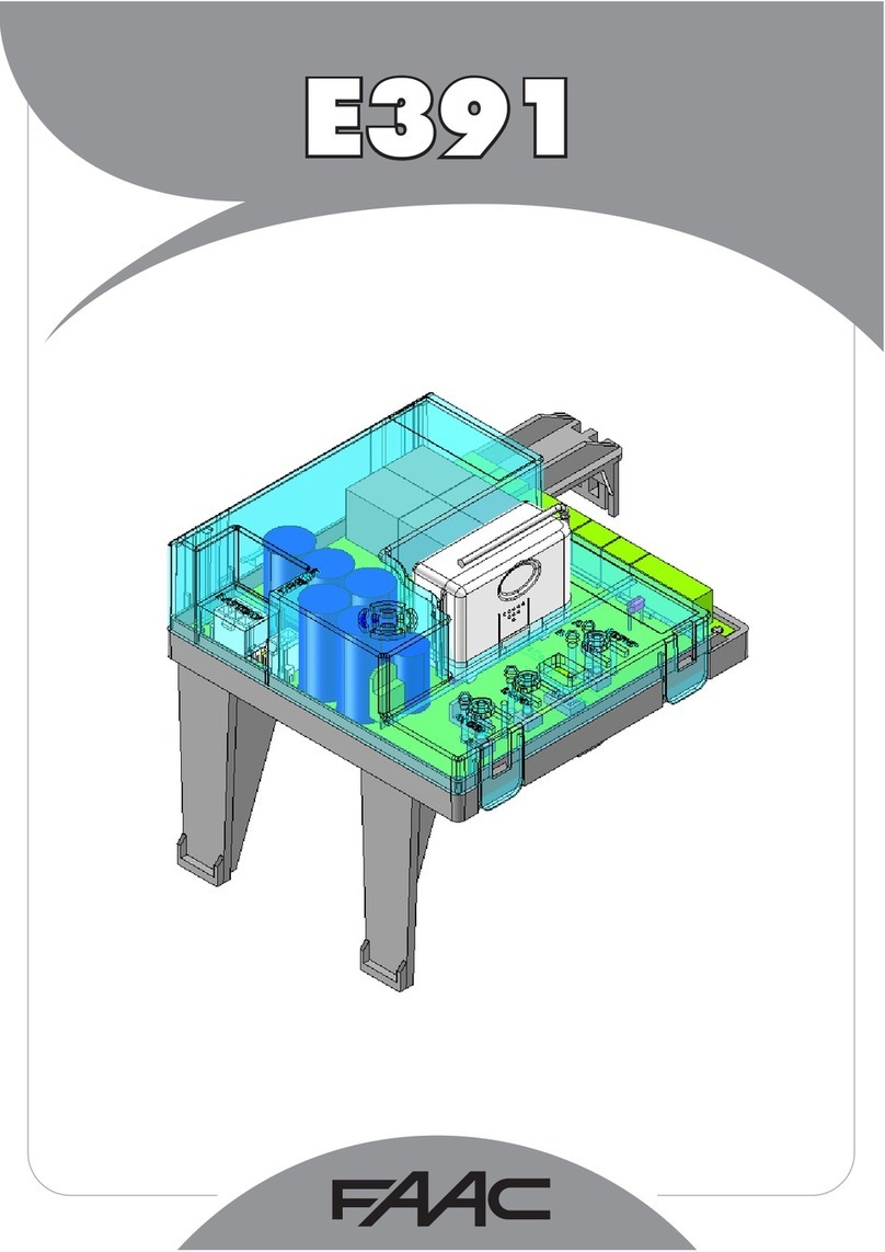
FAAC E850S User manual

Kit E850S
Translation of the original instructions

FAAC S.p.A. Soc. Unipersonale
Via Calari, 10 - 40069 Zola Predosa BOLOGNA - ITALY
Tel. +39 051 61724 - Fax +39 051 758518
www.faac.it - www.faacgroup.com
© Copyright FAAC S.p.A. dal 2017. Tutti i diritti riservati.
Nessuna parte di questo manuale può essere riprodotta, archiviata, distribuita a terzi
né altrimenti copiata, in qualsiasi formato e con qualsiasi mezzo, sia esso elettronico,
meccanico o tramite fotocopia, senza il preventivo consenso scritto di FAAC S.p.A.
Tutti i nomi e i marchi citati sono di proprietà dei rispettivi fabbricanti.
I clienti possono effettuare copie per esclusivo utilizzo proprio.
Questo manuale è stato pubblicato nel 2017.
© Copyright FAAC S.p.A. from 2017. All rights reserved.
No part of this manual may be reproduced, archived, distributed to third parties nor
copied in any other way, in any format and with any means, be it electronic, mechanical
or by photocopying, without prior written authorisation by FAAC S.p.A.
All names and trademarks mentioned are the property of their respective manu-
facturers.
Customers may make copies exclusively for their own use.
This manual was published in 2017.
© Copyright FAAC S.p.A. depuis 2017. Tous droits réservés.
Aucune partie de ce manuel ne peut être reproduite, archivée ou distribuée à des tiers
ni copiée, sous tout format et avec tout moyen, qu’il soit électronique, mécanique ou
par photocopie, sans le consentement écrit préalable de FAAC S.p.A.
Tous les noms et les marques cités sont la propriété de leurs fabricants respectifs.
Les clients peuvent faire des copies pour leur usage exclusif.
Ce manuel a été publié en 2017.
© Copyright FAAC S.p.A. ab dem 2017. Alle Rechte vorbehalten.
Kein Teil dieses Handbuchs darf reproduziert, gespeichert, an Dritte weitergegeben
oder sonst auf eine beliebige Art in einem beliebigen Format und mit beliebigen
Mitteln kopiert werden, weder mit elektronischen, noch mechanischen oder durch
Fotokopieren, ohne die Genehmigung von FAAC S.p.A.
Alle erwähnten Namen und Marken sind Eigentum der jeweiligen Hersteller.
Die Kunden dürfen nur für den Eigengebrauch Kopien anfertigen.
Dieses Handbuch wurde 2017 veröffentlicht.
© Copyright FAAC S.p.A. del 2017. Todos los derechos están reservados.
No puede reproducirse, archivarse, distribuirse a terceros ni copiarse de ningún modo,
ninguna parte de este manual, con medios mecánicos o mediante fotocopia, sin el
permiso previo por escrito de FAAC S.p.A.
Todos los nombre y las marcas citadas son de propiedad de los respectivos fabricantes.
Los clientes pueden realizar copias para su uso exclusivo.
Este manual se ha publicado en 2017.
© Copyright FAAC S.p.A. van 2017. Alle rechten voorbehouden.
Niets uit deze handleiding mag gereproduceerd, gearchiveerd, aan derden openbaar
gemaakt of op andere wijze gekopieerd worden, in om het even welke vorm en
met geen enkel middel, noch elektronisch, mechanisch of via fotokopiëren, zonder
schrfitelijke toestemming vooraf van FAAC S.p.A.
Alle vermelde namen en merken zijn eigendom van de respectievelijke fabrikanten.
De klanten mogen kopieën maken die enkel voor eigen gebruik bestemd zijn.
Dez handleiding werd in 2017 gepubliceerd.

Kit E850S 3 532181 - Rev.A
Translation of the original instructions ENGLISH
CONTENTS
1. INTRODUCTION TO THE INSTRUCTION MANUAL........... 4
1.1 Meaning of the symbols used................................... 4
1.2 Tools required ..................................................... 4
2. KIT E850S............................................................ 5
2.1 Intended use ...................................................... 5
2.2 Unauthorised use................................................. 5
2.3 Technical characteristics ......................................... 5
2.4 Component identification ....................................... 5
3. PRELIMINARY OPERATIONS..................................... 7
3.1 Removing the cover .............................................. 7
3.2 Disconnecting the electronic board E850...................... 7
3.3 Removing the original frame.................................... 8
3.4 Disconnect the limit switches ................................... 8
4. INSTALLATION ..................................................... 9
4.1 Connecting the new limit switch cable ........................ 9
4.2 Connecting the new electric motor cable ..................... 9
4.3 Installing the new frame........................................10
4.4 Removing the plastic covers....................................10
4.5 Connections to the board E850S...............................11
5. STARTUP.......................................................... 14
5.1 Manual operation................................................14
5.2 Limit switch adjustment ........................................15
5.3 Programming ....................................................17
6. PUTTING INTO SERVICE ........................................ 18
6.1 Final checks ......................................................18
7. DIAGNOSTICS .................................................... 18
7.1 LEDs check .......................................................18
7.2 Status of the automation .......................................18
EU DECLARATION OF CONFORMITY
The Manufacturer
Company name: FAAC S.p.A. Soc. Unipersonale
Address: Via Calari, 10 - 40069 Zola Predosa BOLOGNA - ITALY
hereby declares on his sole responsibility that the following products:
Description: The control board
Model: E850S
comply with the following applicable EU legislations:
2014/35/EU
2014/30/EU
2011/65/EU
Furthermore, the following harmonised standards have been applied:
EN 60335-1:2012 + A11:2014
EN61000-6-2:2005
EN61000-6-3:2007 + A1:2011
Bologna, Italy 20-03-2017 CEO

Kit E850S 4 532181 - Rev.A
Translation of the original instructions ENGLISH
1. INTRODUCTION TO THE INSTRUCTION MANUAL
1.2 TOOLS REQUIRED
1 Symbols: notes and warnings on the instructions
FWARNING ELECTRIC SHOCK HAZARD -The procedure or step described must
be carried out following the instructions provided and according to the
applicable safety regulations
!WARNING, PERSONAL INJURY HAZARD OR RISK OF DAMAGE TO COMPO
NENTS - The procedure or step described must be carried out following the
instructions provided and according to the applicable safety regulations.
WARNING - Details and specifications that must be complied with in order to
ensure that the system operates correctly.
FIGURE E.g.: 1-3 see Figure 1 - detail 3.
TABLE E.g.: 1 see Table 1.
§CHAPTER/SECTION E.g.: §1.1 see section 1.1.
Automatic operation - automation locked
Manual operation - automation unlocked
1.1 MEANING OF THE SYMBOLS USED
2 Symbols: safety signs and symbols (EN ISO 7010)
GENERIC HAZARD
Personal injury hazard or risk of damage to components
ELECTROCUTION HAZARD
Risk of electric shock from live parts
CRUSHING HAZARD
Risk of crushing of hands/feet due to the presence of heavy parts
CUTTING/AMPUTATION/PIERCING HAZARD
Cutting hazard due to the presence of sharp components or the use of
pointed/sharp tools (drill)
SHEARING HAZARD
Risk of shearing due to moving parts
RISK OF IMPACT/CRUSHING
Risk of impact or crushing due to moving parts
RISK OF TRIPPING
Risk of tripping over due to the presence of thresholds higher than 5mm
3 Symbols: personal protective equipment
Personal protective equipment must be worn to protect against hazards (e.g. crushing,
cutting, shearing etc.):
Obligation to wear work gloves
Obligation to wear safety footwear
! Use appropriate tools and equipment in working environments which
comply with applicable legislation.
4 Symbols: work tools
8 ; 19
HEX SPANNER of size indicated
FLAT SCREWDRIVER
PHILLIPS SCREWDRIVER
4
ALLEN KEY with ROUND HEAD of the size(s) indicated
ELECTRICIAN'S SCISSORS
WIRE STRIPPER/TERMINAL CRIMPER

Kit E850S 5 532181 - Rev.A
1
1
2
3
4
5
Translation of the original instructions ENGLISH
2.4 COMPONENT IDENTIFICATION
5 Components
1New frame
2Electronic board E850S with plastic covers
3New cable for the integrated limit switches
4New cable for the electric motor
5Fasteners
2. KIT E850S
2.1 INTENDED USE
The Kit is specifically for the FAAC C850 gearmotor.
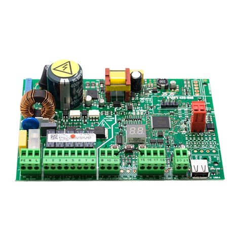
The Kit allows you to replace the electronic board E850 and inverter
with the electronic board E850S.
2.2 UNAUTHORISED USE
-Uses other than the intended use are prohibited.
-It is prohibited to power the system with energy sources other
than those specified.
-It is prohibited to integrate commercial systems and/or equip-
ment other than those specified, or use them for purposes not
envisaged and authorised by the corresponding manufacturers.
-It is prohibited to use and/or install accessories which have not
been specifically approved by FAAC S.p.A.
-It is prohibited to use the automation before performing com-
missioning.
-It is prohibited to use the automation in the presence of faults
which could compromise safety.
-It is prohibited to use the automation with the fixed and/or
mobile guards removed or altered.
-Do not allow water jets of any type or size to come into direct
contact with the gearmotor.
-Do not expose the gearmotor to corrosive chemical or atmos-
pheric agents.
-Do not use the automation unless the area of operation is free
of persons, animals or objects.
-Do not enter/remain in the area of operation of the automation
while it is moving.
-Do not try to prevent the movement of the automation.
-Do not climb on, hold onto or let yourself be pulled by the
leaf. Do not climb onto or sit on the gearmotor.
-Do not allow children to approach or play in the area of operation
of the automation.
-Do not allow the control devices to be used by anyone who is
not specifically authorised and trained to do so.
-Do not allow the control devices to be used by children or persons
with mental and physical deficiencies unless they are supervised
by an adult who is responsible for their safety.
2.3 TECHNICAL CHARACTERISTICS
The Kit E850S includes:
-the electronic board E850S for controlling the gearmotor C850
-a new support frame for the board E850S
-a new cable for connecting the integrated limit switches
-a new cable for connecting the electric motor
The electronic board E850S has an integrated:
-inverter for programming the opening and closing speeds
independently
-fan for cooling the inverter
-LCD display and 2 buttons for programming the functions

Kit E850S 6 532181 - Rev.A
PE N L
BRAKE
BRAKE
LAMP
LAMP
OPEN B
OPEN A
SAFE
OPEN
FSW CL
FSW OP
STOP
LOCK
COM
-
W.L.
COM
+24V
NC
NO
PE
N
L
U
V
W
W
V
U
MOTOR
OPEN SX OPEN DX
LIMIT
SWITCH SX
FAN
FAIL SAFE
M
3
OP
R.OP
CL
R.CL
LIMIT
SWITCH DX
ENTER UP/DWN
RADIO
RESET
T10A
230V~
30W
24V
0.2A
+24V
0.5A max
+
-
2
F1
J1
J2
J3 J4
J5 JP1
DISPLAY
P1 P2
J7
J6
JP2
JP3
DL5
DL7
DL6
DL8
J8
P3
DL9
DL10
DL11
DL12
DL13
DL14
DL15
Translation of the original instructions ENGLISH
BOARD E850S
COMPONENTS
E850S
J 1 Power supply terminal board
J 2 Electric brake and flashing light terminal board
J 3 Left opening motor terminal board
J 4 Right opening motor terminal board
J 5 Control devices terminal board
J 6 Failsafe terminal board
J 7 LED and accessories power supply terminal board
J 8 Cooling fan terminal board
JP 1 Connector (5 pin) for radio/decoder board
JP 2 Left opening limit switch connector
JP 3 Right opening limit switch connector
DISPLAY Programming display
P 1 ENTER button
P 2 UP/DWN button
P 3 RESET button
F 1 Power supply fuse T10A
DL 5 Opening limit switch status LED
DL 6 Closing limit switch status LED
DL 7 Opening deceleration status LED
DL 8 Closing deceleration status LED
DL 9 OPEN input status LED
DL 10 OPEN B input status LED
DL 11 OPEN A input status LED
DL 12 SAFE input status LED
DL 13 FSW CL input status LED
DL 14 FSW OP input status LED
DL 15 STOP input status LED
6 Board technical data E850S
Power supply voltage 230 V~(+6% -10%) 50/60 Hz
Max power 18 W
Accessories output voltage 24 V
Max. motor power 1.5 KW
Max. accessories load 500 mA
Max. flashing light load 30 W (230V~)
Ambient operating temperature -20 °C - +55 °C

Kit E850S 7 532181 - Rev.A
3
5
6
7
4
1
1
2
4
3
4
4
Translation of the original instructions ENGLISH
3. PRELIMINARY OPERATIONS
RISKS
PERSONAL PROTECTIVE EQUIPMENT
F Always shut off the power supply before performing any work. If
the disconnect switch is not in view, apply a warning sign stating
“WARNING - Maintenance in Progress”.
3.1 REMOVING THE COVER
1. Unscrew the 4 screws and remove the cover (3).
2. Put the cover and the 4 screws to one side.
3.2 DISCONNECTING THE ELECTRONIC BOARD
E850
1. Disconnect the power supply and earth wires from the C850
(4-1).
2. Unscrew the screws of the plastic cover of the E850 board. Re-
move the plastic cover. (5).
3. Disconnect the limit switch cable from the E850 board. Remove
the limit switch cable from the conduit (6).
4. Unscrew the 4 screws of the electric motor junction box and re-
move the cover (7-1). Put the screws and cover to one side.
5. Remove the 3 nuts that connect the cable lugs of the electric motor
(7-2). Put the nuts to one side.
6. Unscrew the electric motor cable gland
(7-3). Remove the electric motor cable from the cable gland
(7-4).
7. Disconnect the remaining wires from the electronic board
E850. Remove the wires from the conduits.

Kit E850S 8 532181 - Rev.A
4 8
4 8
8 19
9
10
11
1
2
3
Translation of the original instructions ENGLISH
3.3 REMOVING THE ORIGINAL FRAME
1. Unscrew the 2 screws and 2 nuts that fasten the frame to the base
of the operator (8-9).
2. Remove the frame from the base of the operator (10).
3.4 DISCONNECT THE LIMIT SWITCHES
1. Unscrew the 2 screws of the limit switch unit cover Remove the
cover (11-1). Put the cover and screws to one side.
2. Unscrew the cable gland from the limit switch unit (11-2).
3. Disconnect the cable lugs from the micro switches and remove
the limit switch cable from the cable gland (11-3).

Kit E850S 9 532181 - Rev.A
13
19 15
16
17
12
14
1
2
Translation of the original instructions ENGLISH
4. INSTALLATION
RISKS
PERSONAL PROTECTIVE EQUIPMENT
4.1 CONNECTING THE NEW LIMIT SWITCH
CABLE
1. Take the cable gland seal from the Kit as shown in 12-1.
2. Take the new limit switch cable included in the Kit. Make a hole
in the cable gland seal. Insert the cable lugs into the cable gland
seal in the direction shown in 12-2.
3. Slide the cable gland seal along the limit switch cable.
4. Insert the cable lugs into the cable gland of the limit switch unit.
(13).
5. Connect the cable lugs to the micro limit switches. Follow the
colour scheme indicated in 14.
6. Tighten the limit switch unit cable gland (15).
4.2 CONNECTING THE NEW ELECTRIC MOTOR
CABLE
1. Take the new electric motor cable included in the Kit.
2. Insert the ring cable lugs into the electric motor cable gland
(16).
3. Connect the ring cable lugs to the electric motor as follows:
U1 Grey/Black
V1 Blue
W1 Brown
YELLOW
EMPTY
EMPTY
EMPTY
EMPTY
WHITE
GREY
GREEN
BROWN

Kit E850S 10 532181 - Rev.A
4 8
4 8
19
20
21
22
18
12
3
Translation of the original instructions ENGLISH
4.3 INSTALLING THE NEW FRAME
1. Place the new frame on the base in the same position as the old
frame 19).
2. Fasten the new frame using the 2 nuts, the 2 screws and the 4
washers included in the Kit (20-21)
4.4 REMOVING THE PLASTIC COVERS
1. Unscrew the 7 fixing screws from the plastic covers of the E850S
board. Remove the plastic covers (22).
2. Put the plastic covers and fixing screws to one side.
4. Tighten the 3 nuts that had been put aside previously onto the
ring cable lugs (18-1).
5. Tighten the electric motor cable gland (18-2).
6. Place the cover on the electric motor junction box. Tighten the
4 screws of the cover that had been put aside previously (18-3).
Table of contents
Other FAAC Control Unit manuals
Popular Control Unit manuals by other brands

Festo
Festo Compact Performance CP-FB6-E Brief description

Elo TouchSystems
Elo TouchSystems DMS-SA19P-EXTME Quick installation guide

JS Automation
JS Automation MPC3034A user manual

JAUDT
JAUDT SW GII 6406 Series Translation of the original operating instructions

Spektrum
Spektrum Air Module System manual

BOC Edwards
BOC Edwards Q Series instruction manual

KHADAS
KHADAS BT Magic quick start

Etherma
Etherma eNEXHO-IL Assembly and operating instructions

PMFoundations
PMFoundations Attenuverter Assembly guide

GEA
GEA VARIVENT Operating instruction

Walther Systemtechnik
Walther Systemtechnik VMS-05 Assembly instructions

Altronix
Altronix LINQ8PD Installation and programming manual