evenes Gelbi D 4.2 User manual
Operating manual and assembly
Air / Water Heat Pump
Version: 4_07_2020

2

3
1. Description of the Heat Pump ............................................................................................................................. 4
2. Construction of the Heat Pump .......................................................................................................................... 4
3. Installin of the Heat Pump ................................................................................................................................ 4
4. Description of controller functions ..................................................................................................................... 8
5. Main menu .......................................................................................................................................................... 9
6. Fitters menu ...................................................................................................................................................... 11
7. Service menu ..................................................................................................................................................... 15
8. Standby mode ................................................................................................................................................... 19
9. Security and Alarms .......................................................................................................................................... 20
10. Maintenance ................................................................................................................................................... 22
11. SG Ready function ........................................................................................................................................... 22
12. The procedure after the shelf life of the device.............................................................................................. 22
13. Electrical dia ram ............................................................................................................................................ 23
14. Hydraulic dia rams .......................................................................................................................................... 25
15. Technical data ................................................................................................................................................. 28
Start-up protocol of the heat pump GELBI D4.2 .................................................................................................. 30
Start-up protocol of the heat pump GELBI D4.2 ................................................................................................... 31
4
1. Description of the Heat Pump
Heat pump GELBI D4.2 is a device desi ned for preparation domestic hot water. It uses the rotary
screw compressor optimised for hi h condensation temperatures, i.e. enablin heatin to hi h
temperature. The air flow is forced via the finned coil by modern, powerful and ener y efficient fan.
Water is heated in the SWEP plate exchan er made of stainless steel. Hot water circulation is forced
by WILO circulatin pump adapted also to work directly with tap water. The correct operation of the
heat pump is supervised by a controller with an al orithm optimised for the desi n of the GELBI D4.2
heat pump. The housin is made of ABS plastic. All the above mentioned characteristics and
components comprise the hi h quality and efficiency of the heat pump.
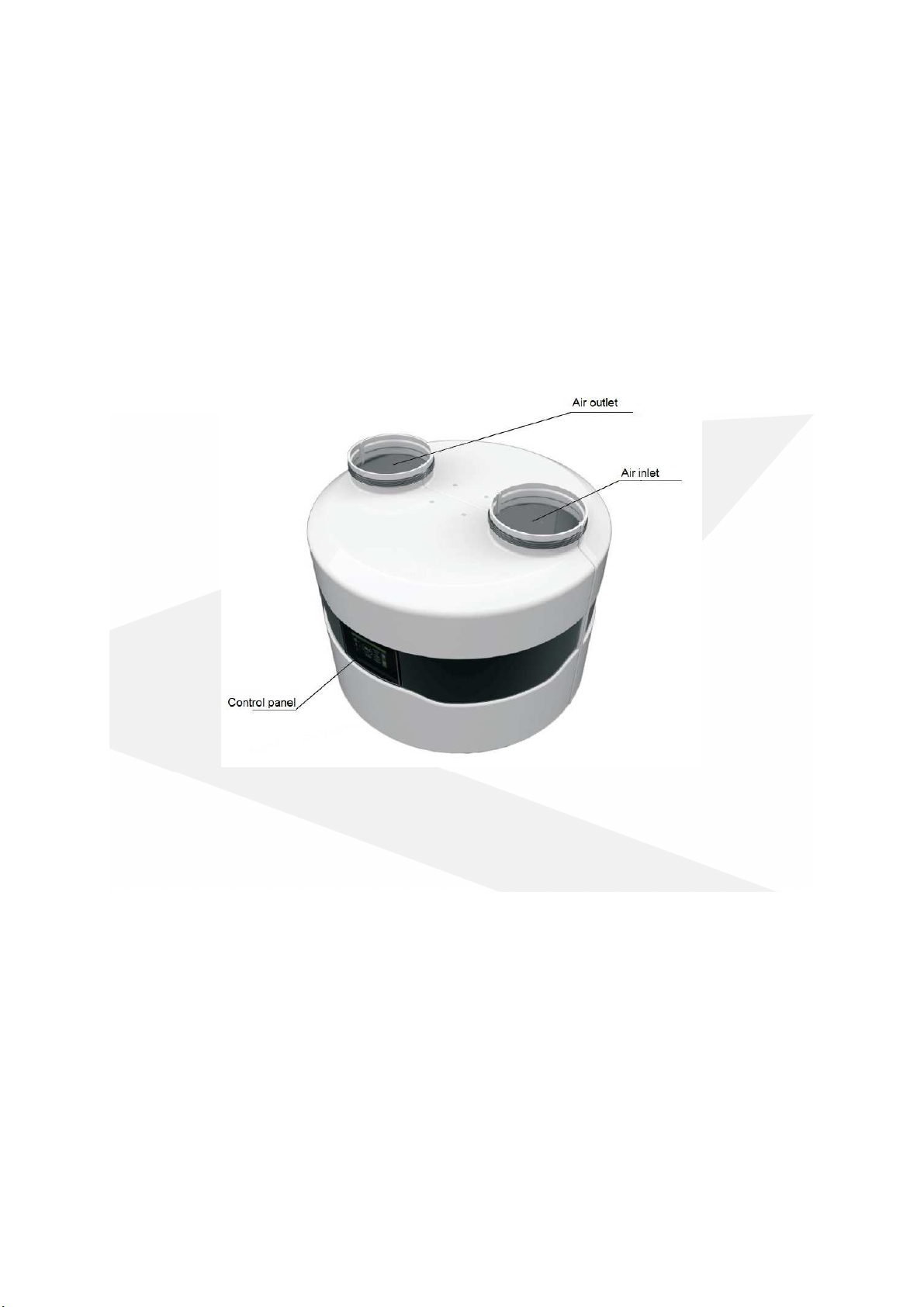
2. Construction of the Heat Pump
Power supply cord and tank and buffer sensor are located at the back of the device.
. Installing of the Heat Pump
.1 Precautions during installation of the device
Installation of the heat pump should be performed by a person with appropriate qualifications in the
field of heatin and coolin devices. The country-specific health and safety re ulations must be
observed durin installation.
.2 Installation recommendations
GELBI D4.2 heat pump should be installed in a room where the temperature does not drop below +
5°C. If the temperature may fall below +5°C, the water circuit between the heat pump and the
stora e tank must be emptied and the system has to be blown out well, e. . with compressed air.
During the installation process heat pump should be levelled by adjusting height of the legs. Failure
to comply with this recommendation may result in a defective work and eventually damage to the
equipment.

5
Keep a distance from the barriers (ceilin walls, etc.) for trouble-free maintenance of the heat pump.
In the bottom part of the heat pump housin there is a condensate drain connection to which the
drain hose must be connected. It is recommended to drain the condensate into the sewa e system
and to use a siphon.
. Connection of hydraulic circuit
The heat pump has a built-in automatic air vent that ensures ventin of the condenser and the
heatin loop.
The pipeline between the heat pump and the stora e tank must have an internal diameter of 20 mm.
The heat pump must be connected to the system via flexible hoses.
On the return pipe line install the strainer filter !!!
The pipelines should be insulated on the whole len th!!!
.4 Connection of air ducts
The heat pump has two connections for connectin the air ducts. The internal diameter of the air
ducts should be min. 250 mm. It is recommended to install insulated air ducts. The maximum
len ths of the air ducts: 8m
Note:
- The use of smaller diameter air ducts may result in a decrease in efficiency.
- When connecting air ducts outside the building, it is essential to provide protection
against air circulation in winter (sub-zero temperatures) when the heat pump is out of use.
A coarse ISO filter (ISO Coarse) in accordance with the current ISO 16890 or a G2 class filter
(compatible with the withdrawn standard EN 779: 2012) should be installed on the heat pump
suction duct.
NOTE !!!
•The temperature difference between supply and return of heating circuit should be
set 5-8K
•The heat pump should be connected to the power supply at all times. This applies
when the DHW tank is heated by another heat source. The controller should be in
standby mode. All protective functions are then carried out: condenser protection,
antifreeze protection: DHW and buffer tank, pump antistop function.

6
Air extracted from one room and exhausted to
another room
Air extracted from one room and exhausted
throu h the wall to another room
Air extracted from the outside throu h the wall
and exhausted to the outside throu h the wall
Air extracted
from the outside throu h the wall
and exhausted to the outside throu h the roof
Separation of inlet and exhaust air
Heat pump cooperatin with recuperator

7
The heat pump and the recuperative unit operate independently of each other, therefore the
ventilation ducts should also be separated. This means that when the recuperation is workin and
the heat pump is stopped, then the air flows easily to the ventilation outlet and not to the heat
pump. This would reduce the efficiency of the recuperative air handlin unit fan.
Note: In addition, the intake and ejection of air from the room in which the pump is installed is
permitted. However, this may lead to a reduction in ener y efficiency.
.5 Electrical connection
The heat pump is powered by 1~230V/50 Hz. As a standard it has a plu with a cable of 1.5 m len th.
Important: It is recommended that the electric supply circuit of the heat pump was equipped in the
circuit breaker with characteristic "C" and residual current device with rated differential current
transmission of 0.03A.
Note: All work related with the installation of these elements should be performed by personnel with
the appropriate permissions and qualifications. As a standard there is a possibility of connectin
electric heater up to 1.5 kW. If electric heater with more power is needed, replace the existin power
supply cable.
The sensor cable can be extended up to 5m.
For its extension can be used e. . cable type H03VVV-F 2x0.5mm^2 or with similar parameters.
If the heat pump controller does not work, first check the fuse on the heat pump supply circuit and
then the fuse placed on the control board inside the heat pump. For this purpose, the heat pump
housing must be partially removed.
8
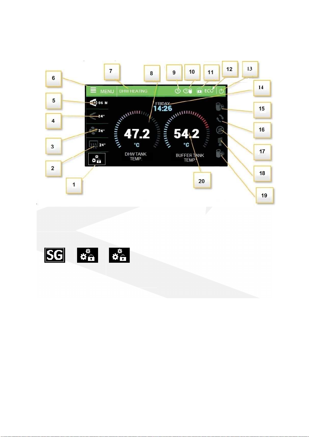
4. Description of controller functions
Description of icons displayed in the controller in the operatin mode:
1
-
Operatin mode of the additional
contact:
9
-
Active weekly schedule of the DHW
10- Active weekly schedule of buffer heatin
11- Active controller lock
12- ECO / ECO PLUS mode
13- STANDBY mode icon
14- Day of the week and current time
15- Operatin status of the tank pump
16- Operatin status of the circulation pump
17- Operatin mode status - "defrost"
18- Operatin status of the heater
19- Operatin status of the buffer pump
20 - Current DHW tank temperature (for
operation with heat buffer, the temperature
measured in the buffer tank)
Active SG
function
End of
heatin by
thermostat
Heatin option
with active
thermostat
2
-
Evaporator temperature
3- Outdoor temperature and fan operation
indication
4- Hot as control temperature and indication of
compressor operation
5- Time to restart the compressor
6- Enter to the controller menu
7- Heat pump mode, alarm notifications
8- Current DHW tank temperature
4.1 Control of the work of executive equipment
The controller controls the operation of the compressor, fan, inte rated circulation pump, circulation
pump and electric heater. The compressor is activated with a delay in relation to the circulation
9
pump and fan – delay compressor parameter. The electric heater operates above ECO-PLUS
temperature, in Party mode and in case of failure.
Attention: The heater is not installed in the device. It is an optional external component, which can
be controlled by the heat pump controller.
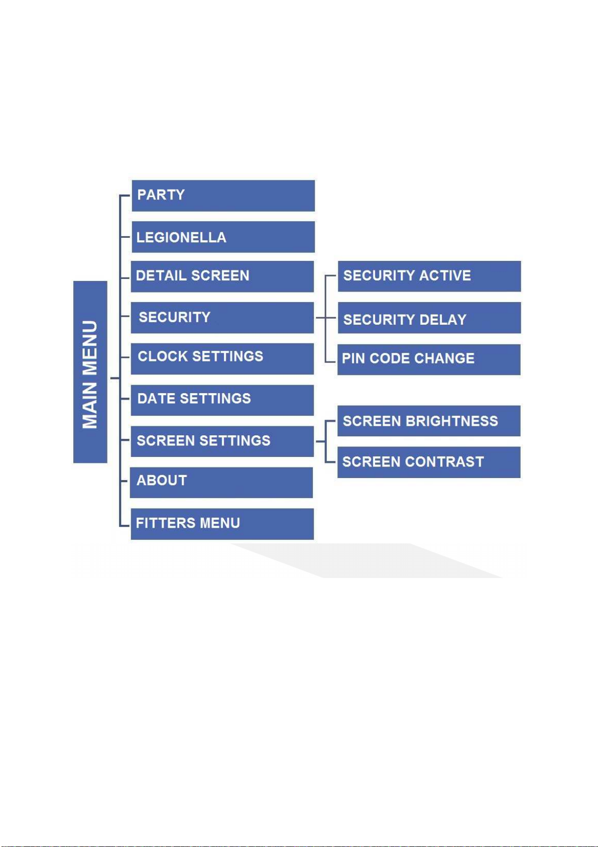
5. Main menu
5.1 Party
When Party mode is activated, the heat pump tank reaches the set temperature as soon as possible.
In this mode, all available heat sources connected to the controller operate simultaneously.
5.2 Legionella
When this function is activated, the boiler heats up to 70°C (factory settin ) and maintains this
temperature for a specified period of time, then returns to normal operation. Any chan es to the
settin s for this function are only possible in the service menu.
5. Detail screen
The detailed screen shows the temperatures measured by the sensors and the status of the pressure
switches.

10
5.4 Security
5.4.1 Security active
Driver blocks access to functions in the controller menu after a defined period of inactivity.
Prevents settin chan es by unauthorized persons or children.
5.4.2 Security delay
If the option Security active is selected, the controller blocks access to the functions of controller
menu after a specified period of inactivity (settin security delay). In order to unblock the controller it
is necessary to enter a four-di it code, which can be defined in the option PIN code change.
5.4. PIN code change
The user sets his own PIN code to the controller.
5.5 Clock setting
Settin the current time in the controller.
5.6 Date setting
Settin the current date in the controller.
5.7 Screen settings
5.7.1 Screen brightness
Screen bri htness settin s.
5.7.2 Screen saver brightness
Set the bri htness level of the screen saver.
5.8 About
The function allows the user to preview the controller information - name of the manufacturer,
software number, and service telephone number.
Table of contents
Popular Heat Pump manuals by other brands


Mitsubishi Electric
Mitsubishi Electric PUZ-SWM60VAA Service manual

Dimplex
Dimplex LI 16I-TUR Installation and operating instruction

Carrier
Carrier WSHP Open v3 Integration guide

TGM
TGM CTV14CN018A Technical manual

Carrier
Carrier 38MGQ Series installation instructions

Kokido
Kokido K2O K880BX/EU Owner's manual & installation guide

Viessmann
Viessmann VITOCAL 300-G PRO Type BW 2150 Installation and service instructions

Carrier
Carrier 48EZN installation instructions

Viessmann
Viessmann KWT Vitocal 350-G Pro Series Installation and service instructions for contractors

Ariston
Ariston NIMBUS user manual

Weishaupt
Weishaupt WWP L 7 Installation and operating instruction

GE
GE Zoneline AZ85H09EAC datasheet