
Eurobil FLY-TN Operation manual

EUROBIL
INSTRUCTIONS FOR USE AND
INSTALLATION
Display
FLY-TN
EXTENDED / NUMBER KEYBOARD
Page 1

EUROBIL
INSTRUCTIONS OF USE AND INSTALLATION
Display FLY TN (extended / number keyboard)
1 28/6/2004 CALIBRATION MODE
0 11th JULY 2003 ISSUE
No. of REV. DATE REASON OF REVISION
Page 2

EUROBIL
CONTENTS
1TECHNICAL CHARACTERISTICS __________________________________________________________ 4
2CONNECTIONS __________________________________________________________________________ 5
2.1 INTERNAL CONNECTIONS OF THE INSTRUMENT _______________________________________ 5
2.2 EXTERNAL CONNECTIONS ___________________________________________________________ 5
2.2.1 Power Supply _____________________________________________________________________ 5
2.2.2 Load cells (platform / balance) ________________________________________________________ 6
2.2.3 Serial interface RS232 ______________________________________________________________ 6
2.3 KEYBOARD _________________________________________________________________________ 7
3INSTALLATION ____________________________________________________________________ 8
3.1 GENERAL RULES ____________________________________________________________________ 8
4OPERATIONAL FUNCTIONS: ______________________________________________________________ 9
4.1 SWITCHING THE INSTRUMENT ON/OFF ________________________________________________ 9
4.2 AUTOMATIC ZERO SETTING __________________________________________________________ 9
4.3 AUTOMATIC TARE___________________________________________________________________ 9
4.4 CLEARING THE TARE _______________________________________________________________ 10
4.5 SELECTING THE DISPLAY OF NET WEIGHT / PIECES ___________________________________ 10
4.6 PRINTING THE WEIGHING OPERATION _______________________________________________ 10
4.7 SETTING PRESET TARES_____________________________________________________________ 10
4.8 SELECTING STORED TARES _________________________________________________________ 11
4.9 SETTING CODES ____________________________________________________________________ 11
4.10 SAMPLING PIECES __________________________________________________________________ 11
4.11 INSERTING THE UNITARY AVERAGE WEIGHT_________________________________________ 12
4.12 PIECE COUNTER ____________________________________________________________________ 12
4.13 PRINTING TOTALS __________________________________________________________________ 12
4.14 DISPLAY TOTAL ___________________________________________________________________ 13
4.15 CHECKING THE CHARGING LEVEL OF THE BATTERY __________________________________ 13
4.16 LOCKING TARE_____________________________________________________________________ 13
5ENTERING THE PROGRAMMING MENU ___________________________________________________ 14
5.1 PROGRAMMING PRESET TARES______________________________________________________ 15
5.2 PROGRAMMING THE PROGRESSIVE NUMBER OF WEIGHING OPERATIONS ______________ 16
5.3 PROGRAMMING-STORING A UAW____________________________________________________ 16
6CONTROL OF COMMUNICATIONS ________________________________________________________ 17
6.1.1.1 Type of protocol ______________________________________________________________ 18
6.1.1.2 Network address ______________________________________________________________ 18
6.2 COMMUNICATION PROTOCOLS ______________________________________________________ 19
6.3 LIST OF COMMANDS ________________________________________________________________ 19
6.4 RECORD TRACKS ___________________________________________________________________ 20
7CALIBRATING THE INSTRUMENT ________________________________________________________ 21
7.1 Entering the calibration mode____________________________________________________________ 21
7.2 Setting the metrologic parameters ________________________________________________________ 22
7.2.1 Setting the capacity________________________________________________________________ 22
7.2.2 Setting the limit of the first weighing range (for multi-interval instruments)____________________ 22
7.2.3 SETTING THE DIVISION _________________________________________________________ 22
7.2.4 Adjusting zero ___________________________________________________________________ 23
7.2.5 Adjustment of Sample Weight _______________________________________________________ 23
7.2.6 Digital filter _____________________________________________________________________ 23
7.2.7 Stability standards_________________________________________________________________ 24
7.2.8 Automatic zero setting field at the switching on (percentage of capacity) ______________________ 24
7.2.9 Zero tracking (tenths of divisions) ____________________________________________________ 25
7.2.10 Zero tracking (intervention time) _____________________________________________________ 25
7.3 Compensation of gravitational variation____________________________________________________ 25
7.3.1.1 Gravity (g) of the calibration place________________________________________________ 26
7.3.1.2 Gravity (g) of the place of use ___________________________________________________ 26
7.3.2 RESET (resetting metrologic data) ___________________________________________________ 26
Page 3
EUROBIL
1 TECHNICAL CHARACTERISTICS
Power supply of the instrument Battery of 6 Vdc – External power supply of 230 Vac 7 Vdc
Maximum absorption 8 W
Operating temperature -10°C to +40°C (max. humidity: 85%, without condensation)
Storing temperature -20°C to +50°C
Display (max) 6 digits - red 7-segment LEDs (h 20 mm)
LEDs of indication (max) 4 red LEDs, with diameter of 5 mm
Keyboard 18 touch sensitive keys
Switching on / off from keyboard
Check of battery Display of the charging level, with automatic switching off.
Overall dimensions 160 mm x 95 mm x 60 mm
Connections Screw terminal boards – pitch of 5 mm
Power supply of load cells 5 Vdc / 90 mA (max. 6 cells of 350 Ω), protected from short
circuits
Input sensitiveness 0.5 micro V / div
Internal resolution 24 bits
Number of decimals for weight 0 to 3 decimals
Serial port Rs232c
Max. length of the cable 15 m (Rs232c)
Standard protocols Transmission of weight
Baud rate 9600 bit/s
Page 4
EUROBIL
2 CONNECTIONS
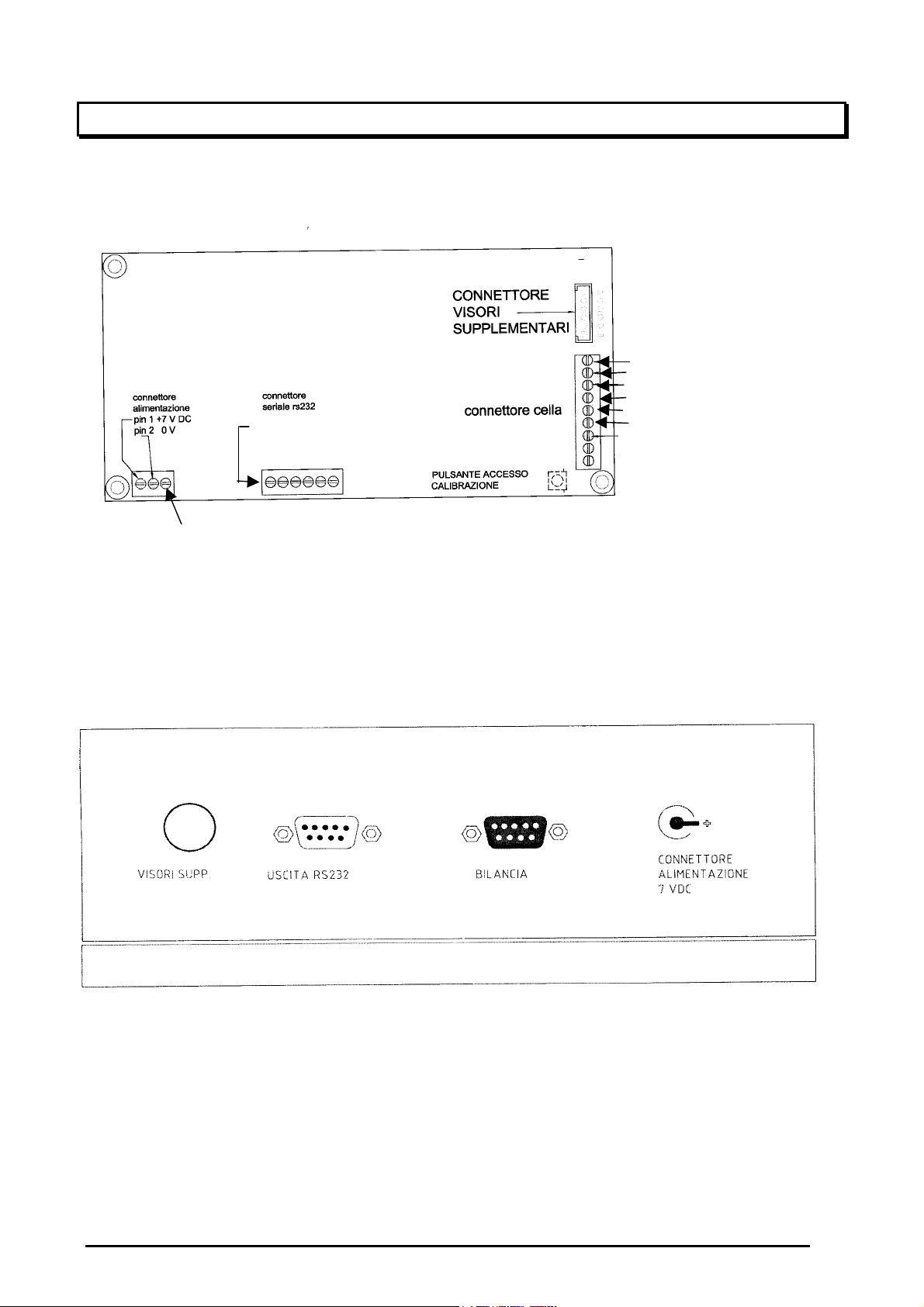
2.1 INTERNAL CONNECTIONS OF THE INSTRUMENT
POWER SUPPLY +
SIGNAL +
SIGNAL –
POWER SUPPLY –
REFERENCE +
REFERENCE -
PIN 1 TX
PIN 2 GND
PIN 3 RX
PIN 3 BATT +
2.2 EXTERNAL CONNECTIONS
The connectors are available in the rear part of the instrument. Identify those of your interest in the
figure shown herebelow.
2.2.1 Power Supply
This instrument will be connected with an EXTERNAL POWER SUPPLY generating an output
voltage of 7 Vdc.
Make sure that this external POWER SUPPLY is connected with a socket of 230Vac 50/60Hz.
Page 5

EUROBIL
2.2.2 Load cells (platform / balance)
Weighing platforms are generally provided with a cable for the connection with the display,
therefore they have a circular 9-pole connector that will be screwed on that which the instrument is
provided with.
If the cable of cells must be wired with the connector, please refer to the diagram indicated
herebelow using a cable with 6 shielded leads whose section complies with the ratio of 0.5 mm² x
70 m.
BALANCE 1
BALANCE 2
9-pole F connectors D-SUB
Load cells
6 leads
Load cells
4 leads
Ground 1 Braid Braid
Power supply + 2 Red Red
Signal + 3 Green Green
Signal - 4 White White
Reference + 5 Purple
Reference - 6 Gray
Power supply - 7 Black Black
Free 8
Free 9
2.2.3 Serial interface RS232
Display COM1
D-SUB 9-pole M
Personal computer
D-SUB 9-pole F
Personal computer
D-SUB 25-pole F
Rxd 2 3 2
Txd 3 2 3
Gnd 5 5 7
Page 6
EUROBIL
2.3 KEYBOARD
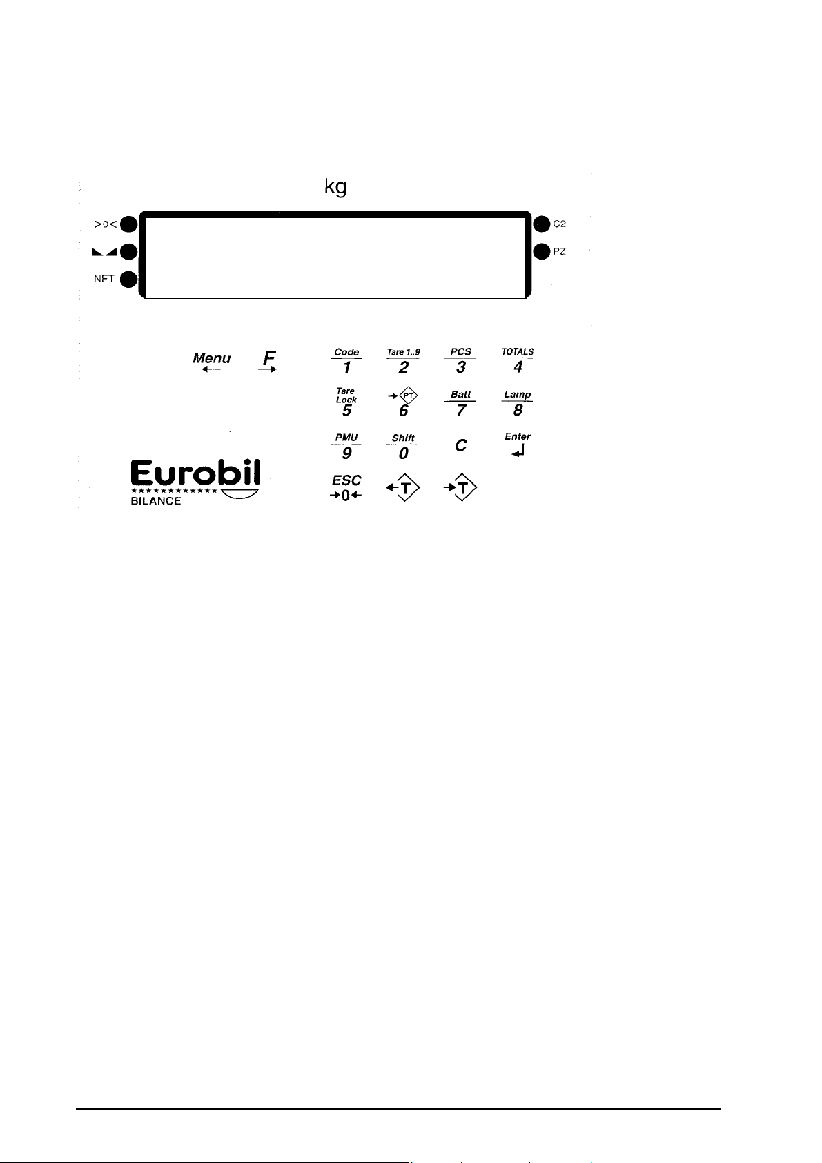
The keyboard consists of 17 keys + 1 ON/OFF function key.
ON
OFF
Main functions:
10 number keys, from 0 to 9
1 ENTER key
1 C key
1 key of semiautomatic zero (->0<-)
1 key of semiautomatic tare ( T)
1 MENU key for entering the programming menu
1 key for switching the NET/PIECES display.
Alternative functions (second function):
The keys described above also have a second function that is selected automatically according to
the enabled function.
Alternative functions assigned to the number keys:
P.TARE (Setting the preset tare)
CODE (Setting the product code 00-99)
TARE 0..9 (Selecting and entering tares previously stored)
PCS (Sampling pieces)
TOTALS (Printing totals)
BATT (Displaying the charging level of the battery)
LAMP (Switching the display backlighting On-Off)
PMU (Setting the Unitary Average Weight)
TARE LOCK (Enabling / disabling the tare lock)
Other functions assigned to the MENU and F keys:
2 cursor keys for scrolling menus and selecting options
Function assigned to the ENTER key
PRINT (Printing the weighing operation)
Function assigned to C
Clearing the tare
Page 7

EUROBIL
3 INSTALLATION
3.1 GENERAL RULES
This instrument will be installed according to the following instructions:
Avoid unstable supporting surfaces and, if necessary, use the special support for wall application,
make sure that the fastening screws have got grip on.
When the instrument is installed in an electric board, make sure that its case does not rest on other
devices included in it.
The connecting leads have to be inserted and screwed onto the internal terminals correctly to avoid
accidental disconnections.
The connecting leads must be laid so that they cannot hamper moving people or machines.
Do not install the instrument near equipment that do not comply with the standards stated by UE
regulations concerning emission of radio-frequency noises.
Avoid any contact of this instrument with corrosive acids.
Do not use sharpened tools to press the buttons of the keyboard.
As regards the installation of the weight detecting system, please comply with the specific
instructions of your own instrument.
Page 8

EUROBIL
4 OPERATIONAL FUNCTIONS:
4.1 SWITCHING THE INSTRUMENT ON/OFF
Switch the instrument on by pressing the key
All the display units will be enabled for some seconds to undergo an operational check.
Then the display will start the zero search.
After searching zero the display is prepared for weighing operations.
If zero search were unsuccessful, some dashes will appear in the central part of the weight
display.
4.2 AUTOMATIC ZERO SETTING
When the display does not indicate zero, being the plate unloaded and no tare inserted, reset
zero by pressing the key
The resetting range is 2% of the maximum capacity.
4.3 AUTOMATIC TARE
Enable the automatic tare by pressing the key
This operation is carried out in any mode ( NET or PIECES), with positive gross weight lower
than the max. capacity. Then the value is cleared with C and when the instrument is switched
off.
Page 9

EUROBIL
4.4 CLEARING THE TARE
Clear the tare by pressing the key
4.5 SELECTING THE DISPLAY OF NET WEIGHT / PIECES
Pressing the key
will alternately select the display of net weight and pieces (pieces, only if a sampling
operations has been carried out).
4.6 PRINTING THE WEIGHING OPERATION
Pressing the key
will lead to this operation in any mode (NET or PIECES), with positive gross weight lower than
the max. capacity.
4.7 SETTING PRESET TARES
Press the following key
Set the digital value and press ENTER
This operation is carried out in any mode ( NET or PIECES), with positive gross weight lower
than the max. capacity. Then the value is cleared with C and when the instrument is switched
off.
Page 10
Table of contents






