Estate Swing Classic Series User manual

INSTRUCTION MANUAL
ESTATESWING.COM
E-S 300 / 302 Classic Series
―WARNING―
Read all instructions before beginning installation
or use of this gate opener.
This operator excerts a high level of force.
Excercise caution at all times and stay clear of the
system during operation.
USER DRIVEN MANUAL*
Any feedback, changes, or advice we are glad
to hear it. Please contact us at
support@estateswing.com
*Estate Swing’s unique user driven manuals are constantly updated by installers and homeowners like yourself. We improve by hearing and applying your feedback.

Estate Swing Summary of Functions
The Estate Swing is only to be used for vehicular swing gates in a Class I setting.
The Estate Swing automated system was designed and built for controlling
vehicle access. Do not use for any other purpose.
The external automation with an electro-mechanical non-reversing linear arm
automates residential swing-leaf gates with leaves of up to 12’ in length. It
consists of an irreversible electro-mechanical operator with built in opening
and closing limits and utilizes a worm screw system. The irreversible system
ensures the gate is mechanical locked when the motor is not operating. A
lock still needs to be installed if security or high winds are a concern. A manual
release makes it possible to move the gate in the event of a power-cut or
fault.
E-S 300 / 302 Classic Series Instruction Manual
A vehicular gate opener (or system) intended for use in a home of one-to-four
single family dwelling, or a garage or parking area associated therewith.
Class I:
Keep this manual safely stored after installation
Serial Number ________________________________
Date of Purchase _____________________________
Place of Purchase ____________________________
Have this information on hand while handling all service
and warranty issues.
For Your Assistance

Table of Contents
The table of contents are listed to assist you locating a desired section. We do
however strongly suggest studying every page of the instruction manual before
attempting installation.
Section 1: Review of Specifications, Warnings, and Tools
Specifications of the Estate Swing and Components 1.1
Parts List 1.2
System Overview & Preliminary Checks 1.3
Tools Needed for Installation 1.4
Section 2: Installation
Manual Operation, Restoring Automation 2.1
IMPORTANT: Determining Setback—Pull to Open 2.2
Installation of Operator—Pull to Open 2.4-.5
IMPORTANT: Determining Setback—Push to Open 2.6
Installation of Operator—Push to Open 2.7-.8
Section 3: Wiring, Jumpers and Receiver
Removing Terminal Strips for Wiring 3.1
Wiring of Operator Arm(s) (Pull & Push to Open) 3.2
Installing Receiver and Setting Transmitters 3.3
Temporary Safety Jumpers & Dip Switch Settings 3.4
Power 3.5
Section 4: Programming the Operator
Adjust limit switches and determine run time 4.1-2
Operating Parameters Settings 4.3
Section 5: Troubleshooting & Accessories
Troubleshooting 5.1-.3
Control Board Overview 5.4-.7
Accessories 5.8
E-S 300 / 302 Classic Series Instruction Manual

Specifications
E-S 300 / 302 Classic Series Instruction Manual
1.1
MODEL Estate Swing E-S300/302
Power Supply 24V AC, 50VA to 120VA
Backup Battery Voltage 24V DC
Current (A) 3
Travel (in.) 13
Cycles per hour 50% Duty Cycle / Aprox. 35
Operating Ambient Temp -20 to 130 F
Protection class IP44
Gate leaf max length (ft.) Up to 12
Gate leaf max weight (lbs.) Up to 600
Operator Type Screw Drive
Operator Weight 14 lbs
Gate Weight/Length Ratio 6' 8' 10' 12'
100lbs X X X X
200lbs X X X X
300lbs X X X X
400lbs XXX
500lbs X X
600lbs X
The above chart represents the maximum weight and length combinations that
this gate opener can handle. The lengths and weights are either for a single gate
or for a single leaf of a dual gate.
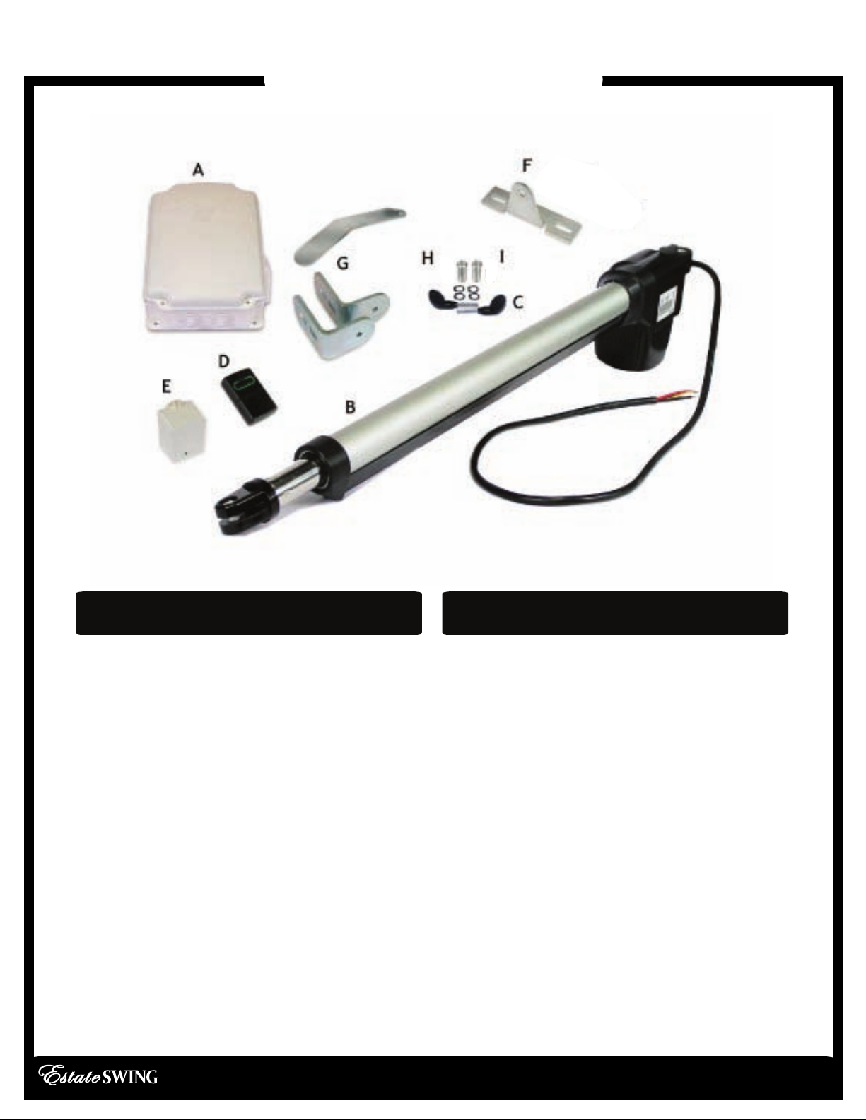
Estate Swing Parts List
E-S 300 / 302 Classic Series Instruction Manual
1.2
Master or Single Operator Slave Operator
(if applicable)
A. Control Box with Control Board and
Receiver
B. Operator Arm with 7’ of Wire
C. Key
D. Transmitter
E. Transformer
F. Gate Mounting Bracket
G. Post Mounting Brackets
H. Connector Pins and C Rings
I. Mounting Hardware
1 - 3/8”x1 3/8” Hex bolts, washer, nut
1 - 5/16”x 1 3/8” Hex bolt, washer, nut
2 - 3/8”x 2” Carriage bolt, washers, nut
1 - 1/4” x 2” Hex bolt, washers, nut
A. N/A
B. Operator Arm with 7’ of Wire
C. Key
D. N/A
E. N/A
F. Gate Mounting Bracket
G. Post Mounting Brackets
H. Connector Pins and C Rings
I. Mounting Hardware
1 - 3/8”x1 3/8” Hex bolts, washer, nut
1 - 5/16”x 1 3/8” Hex bolt, washer, nut
2 - 3/8”x 2” Carriage bolt, washers, nut
1 - 1/4” x 2” Hex bolt, washers, nut
Not Shown: Additional Wire
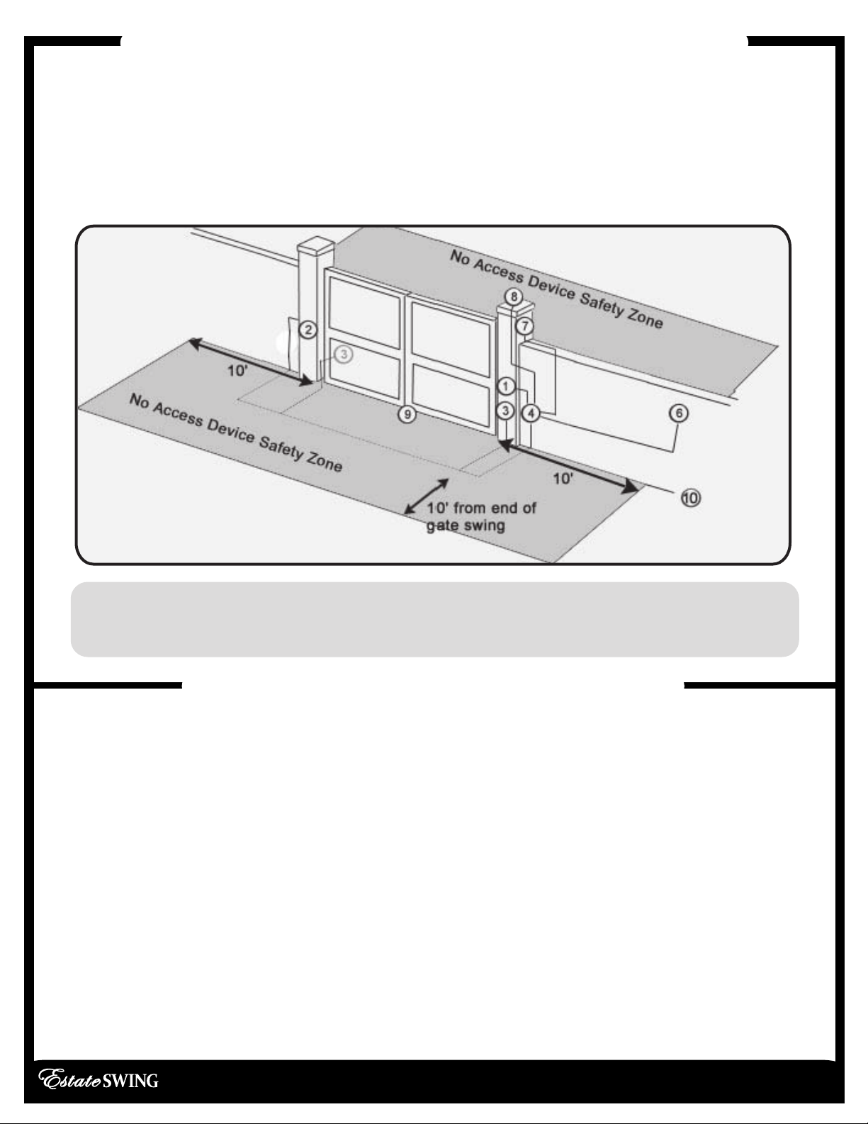
Standard System Overview and Safety Zones
IMPORTANT: Preliminary Checks
E-S 300 / 302 Classic Series Instruction Manual
1.3
The system display to the below is a recommended standard system. Other approved
accessories can be installed. Photo sensors and a flashing light indicating gate
movement is recommended for safety purposes.
1,2 Estate Swing Operator • 3 Photocells (not included) • 4Control board • 5N/A
6Push button opening device (not included) •7 Receiver extension (not included) • 8
24Vdc flashing lamp (not included) • 9Positive stop (not included) • 10 AC transformer
To ensure safety and an efficiently operating automated system, make sure the
following conditions are observed.
• The gate and post must be suitable for being automated. Check that the structure
is sufficiently strong and rigid, and its dimensions and weights conform to those
indicated on page 1.
• Make sure the leaves move smoothly without any irregular friction during entire
travel.
• Make sure the hinges are in good condition. Ball bearing hinges are ideal for gates
weighing over 200 lbs. or over 10’ in length.
• Make sure the gate is plumb and level.
• The fence post must be secured in the ground with concrete. This will prevent
alteration of alignments and leveling during installation and during cycles.
Notes: 1) When laying electrical cables, use appropriate rigid and/or flexible tube
2) Do not run any wires in the same conduit as110 AC power that may be in the
area. This will cause danger of electrocution.
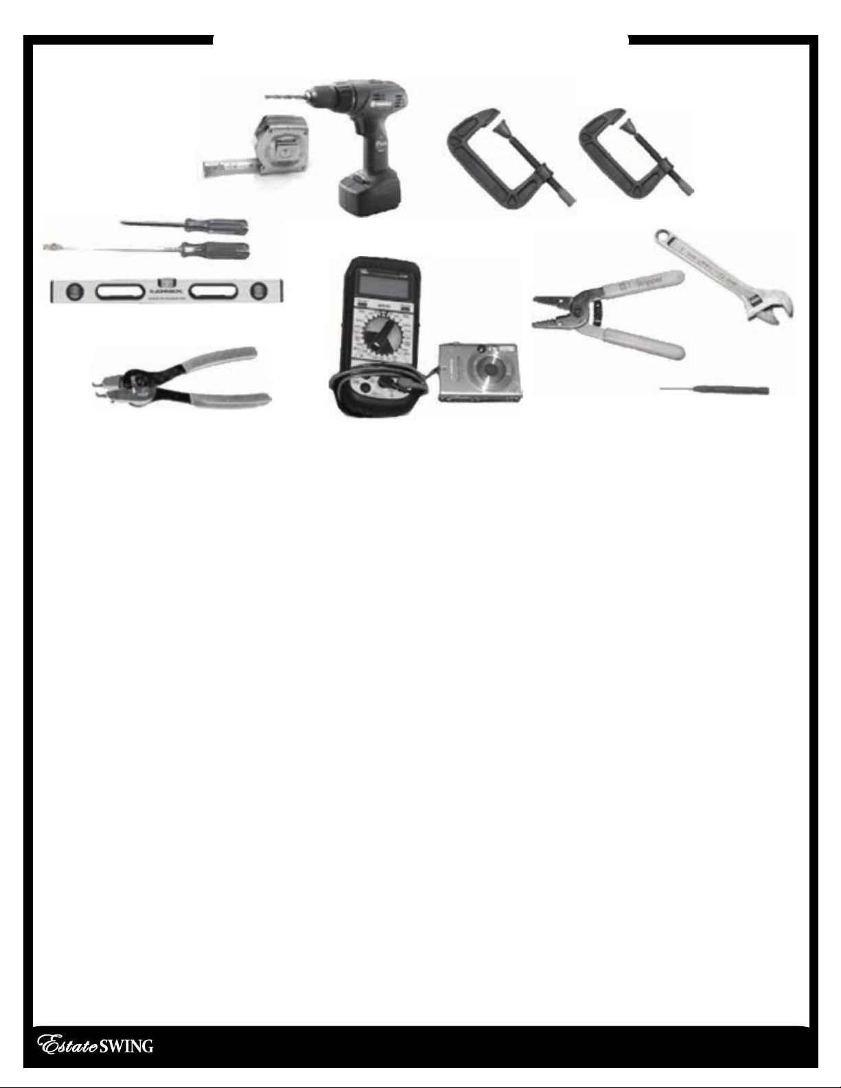
Tools Needed for Installation
E-S 300 / 302 Classic Series Instruction Manual
1.4
Other items may be needed prior to commencing installation. BOLDED items are
necessary to all applications.
• Positive post, bracket or door stop. Although the Estate Swing 300 features built in
limit switches it is highly recommended to have positive stops.
• 16, 14 or 12 gauge, 2 conductor stranded direct burial low voltage wire will be
required to run power to your operator. Length and gauge are determined by
distance between transformer power supply and the control box.
•4 - 3/8” Carriage Bolts will be needed to connect the 2 “L” shaped brackets to the
post. Length will be determined by the size of your posts.
• A metal support bracket may be needed to achieve the appropriate desired
setback. The metal support bracket will be bolted or welded to your post to give a
larger amount of space to mount the provided mounting bracket.
• A voltage meter and digital camera may be necessary to run diagnostic checks.
• If your transformer is going to be plugged into an outdoor outlet you will need to
weatherproof that outlet and transformer. Electrical boxes or plug covers can be
obtained from a local hardware store to accommodate both the plug and
transformer.
• Hardware to attach the control box to a post or fence.
• Watertight connectors for running wires into the control box.
• Power Drill
• Crescent Wrench
• Flat Head Screwdriver
• Hacksaw
• Phillips Head
• Screwdriver
• C-Ring Pliers
• Tape Measure
• Level
• Wire Strippers
• C-clamps
• 3/8”, 1/4”, 5/16” Drill Bits

Manual Operation
Restoring Automation
E-S 300 / 302 Classic Series Instruction Manual
2.1
To maintain the proper performance of your
emergency release - please perform the
following service for your motor once per year.
1. Remove the emergency release cap
2. Spray some WD-40 or other spray lubricant
into the release lock.
3. Allow the lubricant to soak in.
4. Apply a liberal dab of petroleum based jelly
or wheel bearing grease to coat the release
lock.
5. Put the cap securely back in place.
1) Lift lock cover cap off.
2) Insert and turn provided key.
3) The operator can now be pull or
push open.
4) Replace lock cover to protect
lock from water and debris.
To exit manual mode, repeat the
above steps.
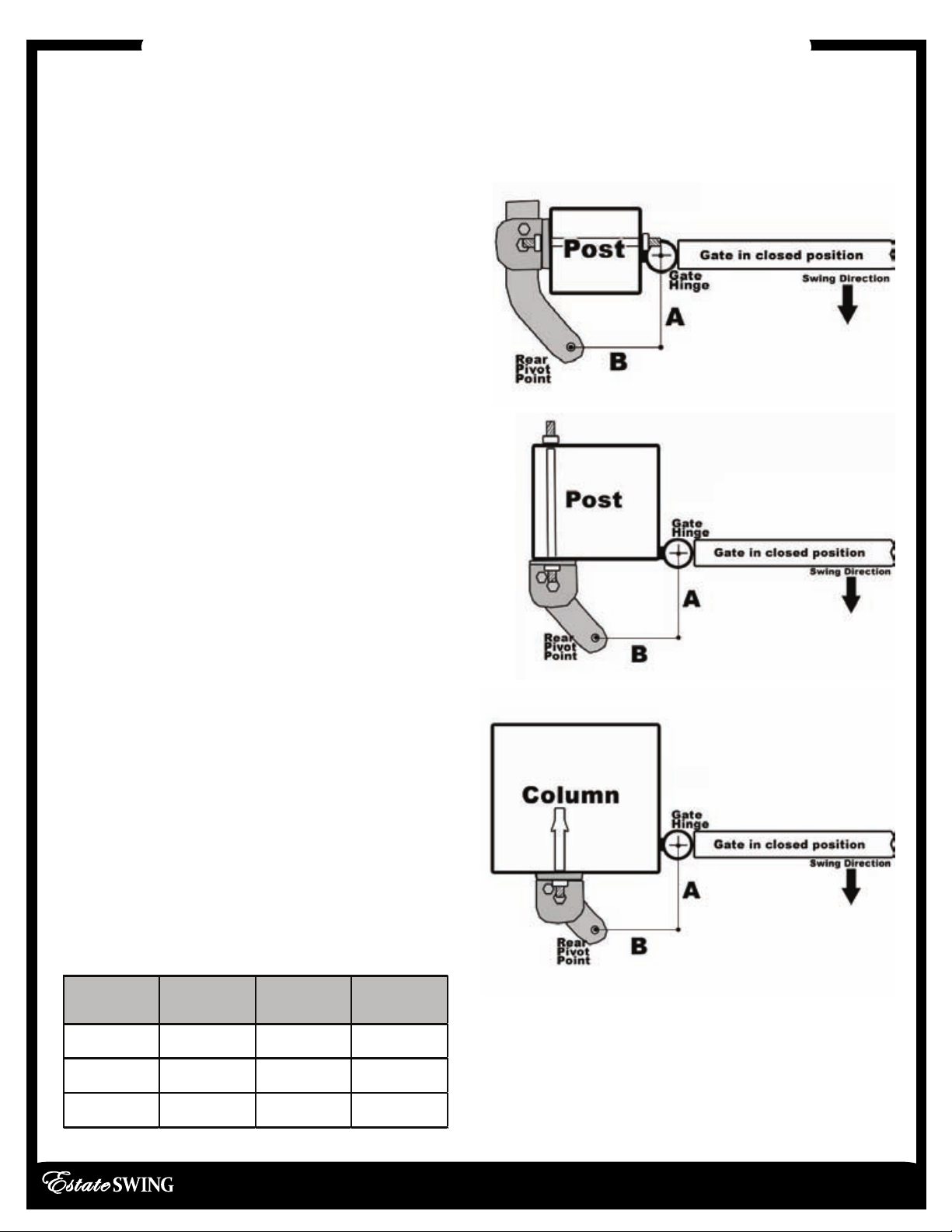
IMPORTANT: Determining Correct Setback
E-S 300 / 302 Classic Series Instruction Manual
2.2
PULL TO OPEN - Standard operation. This means the gate operator is mounted on the
inside of the property and pulls your gate in towards the property. If you are going to use
push to open operation “X” out the next 3 pages and use the push to open section
instructions.
To the right are 3 common
examples of setback mountings.
These are not the only options for
mounting.
There a 3 factors to keep in mind when
finding the setback mounting:
1) The measurements must be correct
from the center of the hinge of the gate
to the center of the hole on the mounting
bracket.
2) There must be clearance for your
opener to attach to your gate in the
closed position.
3) The brackets do not move or pivot
after mounting, if you can achieve the
setback and clearance then bracket
position is inconsequential.
It is best to C-Clamp brackets on and test
arm movement clearance before
permanently attaching them.
Variations to the ideal setback can be
made, so long as the total is less than the
combined measurements for the desired
opening arc and the motor body is more
than 2 inches away from the gate in both
the open and closed position. (setback
variations significantly reduces the length
and weight capacity of the operator)
A B Sum
a
4 ¾" 5 ¼" 10
110°
5 ¼" 5 ¼" 10 1/2 100°
5 ½" 5 ½" 11 90°
To determine the position of the gate
mounting bracket (above is for the post
mounting bracket) refer to step 6 in the
section “Installation of operator”

Installation of Operator—Pull-to-Open
E-S 300 / 302 Classic Series Instruction Manual
2.4
1. Find the proper set back for your operator (from
previous page). Do this by holding the bottom “L”
shaped bracket against the post. Marking its
horizontal positioning on the post using a vertical
line up from the middle of the bracket. Also mark
your angled bracket for positioning on the “L”
shaped bracket. The hole on the end of the
angled bracket should be in the setback position.
2. Cut off the excess length (if any) of the
angled bracket using a hacksaw.
3. Position the angled bracket between the
two “L” shaped brackets in the same
position as when the setback was found.
Clamp the 3 brackets together. Drill through
the angled bracket using the pre-drilled
holes in the “L” shaped brackets using a
3/8” drill bit. Drill through all three brackets
using a 5/16” drill bit in a position behind the
first
hole.
4. Insert a 3/8” x 1” bolt in the center hole
and a 5/16” bolt in the rear hole. Secure
them using the provided nuts and lock
washers.
HINT: Trace the bracket on cardboard and
use the cardboard to make a template.
BEFORE PERMANENTLY ATTACHING ANY BRACKETS, BE
SURE TO TEST ARM MOTION AND CLEARANCE.
Other manuals for Classic Series
1
This manual suits for next models
2
Table of contents
Other Estate Swing Gate Opener manuals

Estate Swing
Estate Swing E-S 1600 Series User manual

Estate Swing
Estate Swing E-S 1600L Series User manual

Estate Swing
Estate Swing E-S 1000H Series User manual

Estate Swing
Estate Swing E-S 1600 Series User manual

Estate Swing
Estate Swing E-S Allegiant Series User manual

Estate Swing
Estate Swing E-SC 400 User manual

Estate Swing
Estate Swing E-S 500 User manual

Estate Swing
Estate Swing E-S 1000H Series User manual

Estate Swing
Estate Swing E-S 300 User manual

Estate Swing
Estate Swing E-SC 1600 Series User manual


