T-SM9e Page 3 of 26
J1 J2 J3 & J5 OPERATION TABLES
READ THESE INSTRUCTIONS BEFORE USE
KeeptheseInstructions in a safe convenientplaceforfuturereference.Readinconjunction
with the relevant Publications detailed in the preliminary information section.
Page
1. PRELIMINARY .. .. .. .. .. 4
2. TECHNICAL DATA .. .. .. .. 5
J1 Operation Table .. .. .. .. .. 5
J2 Operation Table .. .. .. .. .. 6
J3 Operation Table .. .. .. .. .. 7
J5 Operation Table .. .. .. .. .. 8
3. SAFETY NOTES .. .. .. .. .. 9
4. MAINTENANCE .. .. .. .. .. 10
General .. .. .. .. .. .. .. 10
Cleaning, disinfection, care and storage .. 10
Periodic lubrication, checks & adjustment .. 10
Base Components .. .. .. .. .. 10
Castors and wheels .. .. .. .. .. 10
Brakes and brake mechanism .. .. .. 10
Hydraulic cylinder .. .. .. .. .. 10
Gears .. .. .. .. .. .. .. 12
Trendelenburg .. .. .. .. .. 12
Lateral tilt .. .. .. .. .. .. 12
Hinge pin and nut .. .. .. .. .. 13
Lateral screw and nut .. .. .. .. 13
Trend. screw assembly friction collars .. 14
Head section .. .. .. .. .. .. 16
Leg section and catches .. .. .. .. 16
Fault diagnosis and remedies .. .. .. 16
Excessive lateral movement of table top.. 16
Inability to raise table top.. .. .. .. 16
Table top not maintaining height .. .. 17
Operation table will not lower .. .. .. 18
Removal & installation of components .. 20
Replacement of trend, screw .. .. .. 20
Replacing lateral tilt drive belt.. .. 20
Removing hydraulic cylinder from base .. 21
Replacing ram cup washer .. .. .. 21
Removing and cleaning ball valve .. .. 21
Page
Changing hydraulic oil .. .. .. .. 21
Replacing an antistatic wheel in base .. 22
Replacing castor .. .. .. .. .. 22
Replacing worn brake pad .. .. .. 22
Replacing brake quadrant.. .. .. .. 22
Replacing quadrant pinion .. .. .. 22
Replacing broken quadrant pillar .. .. 23
Replacing a control handle .. .. .. 23
Replace push-button catches (leg section) 23
Replacing release handle (head section) .. 24
Replacing release bar (leg section) .. .. 24
Replacing gas spring (head section,J1/2/3) 24
Replacing gas spring unit (leg section) .. 24
Replacing gas spring (head section, J5) .. 24
Hydraulic system operation notes .. .. 26
ILLUSTRATIONS
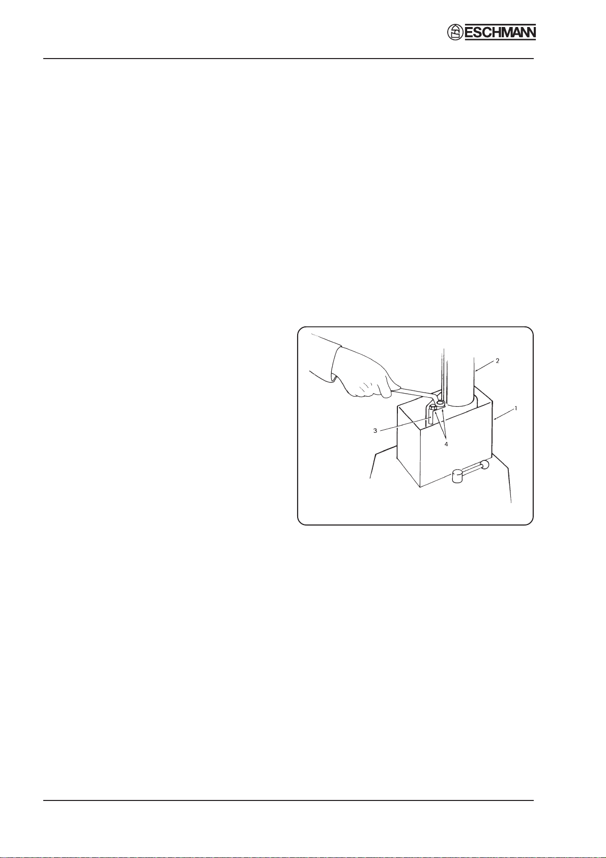
Fig.1 Ram key adjustment .. .. .. .. 10
Fig.2 Base assembly .. .. .. .. .. 11
Fig.3 Gearbox of J2 and J3 .. .. .. .. 12
Fig.4 Hinge pin and nut adjustment .. .. 13
Fig.5 Lateral screw and nut adjustment .. 13
Fig.6 Releasing trend. screw assembly .. 15
Fig.7 Trendelenburg screw assembly .. .. 15
Fig.8 Head (J1, J2 and J3) and leg sections.. 15
Fig.9 Removing hydraulic cylinder .. .. 17
Fig.10 Hydraulic cylinder assembly .. .. 18
Fig.11 Ram release mechanism .. .. .. 19
Fig.12 Drive belt replacement .. .. .. 20
Fig.13 Replacing a control handle .. .. 23
Fig.14 Catch mechanism for leg section .. 24
Fig.15 Removing release handle/bar and
gas spring unit .. .. .. .. .. 25
Fig.16 Head section J5, replacing gas
spring unit .. .. .. .. .. .. 25
Fig.17 Hydraulic system operation .. .. 26
CONTENTS