INSTALLATION INSTRUCTIONS
CAUTION: MAKE SURE POWER IS SWITCHED OFF AT
SERVICE PANEL BEFORE STARTING INSTALLATION.
SECTION 1
Preparing the Fan
1. Unpack fan from the carton and confirm
that all pieces are present. In addition to
the fan you should have:
2 - Collar Assembly (attached)
2 - Mounting Brackets (attached)
1 - Controller (attached)
1 - 24 volt relay box (Included with
unit shipped loose in box)
1 - Instruction/Safety Sheet
2. Choose the location for your fan. To ensure
the best air and sound performance, it is
recommended that the length of ducting
and the number of elbows be kept to a
minimum, the radius of each elbow be as
large as possible for the installation, and
that insulated hard ducting be used. This
fan will require at least 12" of clearance in
the ceiling or wall. The fan mounts using
the provided mounting brackets or can be
surface mounted to a wall or ceiling.
NOTE: The fan must be installed into a location
that can be easily accessed once installed.
3. There are typically three installation options
for the unit:
Intake to Central Grill: The unit is
mounted into the attic space and the
airflow is directed through ducting to a
central location of the home (Figure 1).
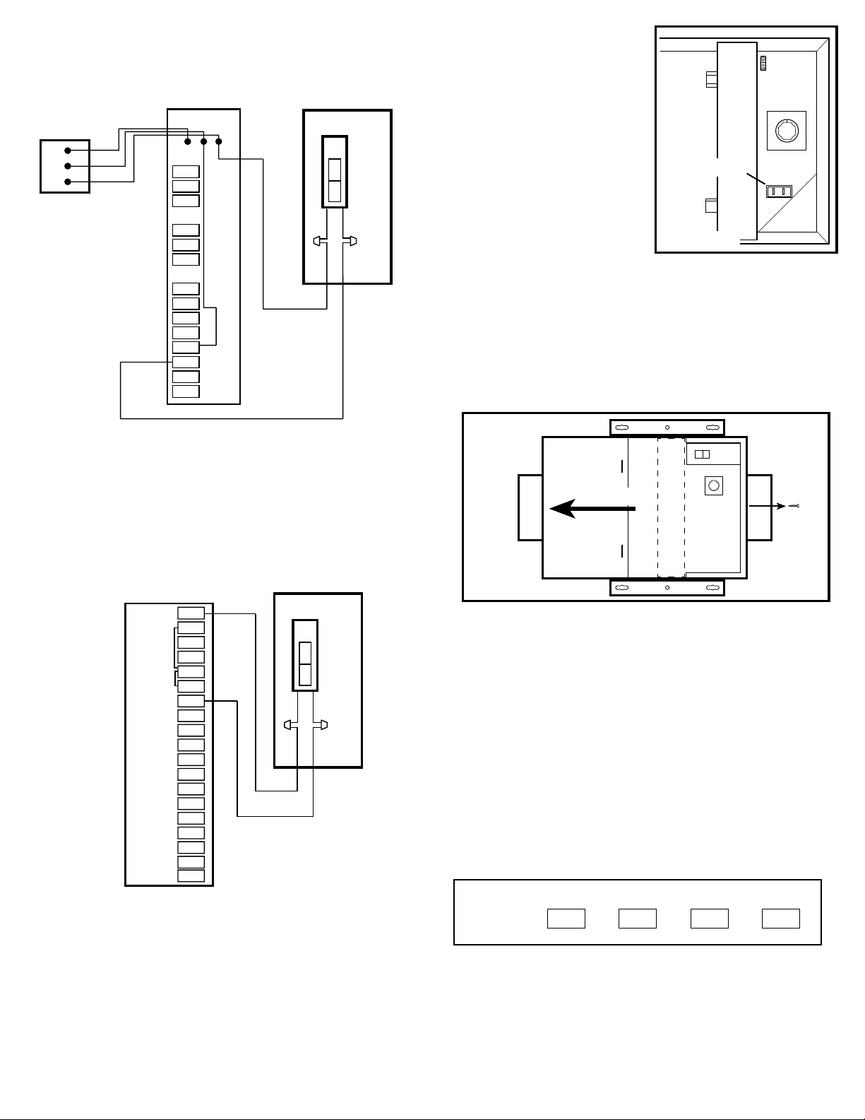
Intake into HVAC System: The unit is
mounted next to the HVAC system with the
airflow directed into the return of the HVAC
system (Figure 2).
Direct Intake: The unit is mounted in a
mechanical room, laundry room or other
less occupied area and the airflow comes
directly into the space without the need
for extra ducting or tying into the HVAC
(Figure 3).
4. No additional vibration deadening materials
are needed for this fan.
SECTION 2
Mounting the Fan
1. Confirm the fan is positioned so the air
flow is in the correct direction.
2a. Surface Mounting: Locate at least one
stud or joist. Place the fan in position so
that the mounting bracket is centered on the stud or joist and make the location for the
four (4) holes. Remove the fan and install properly rated wall/ceiling anchors for the
holes that do not go directly into a joist or stud. Position fan in place and secure with
screws (not included) (Figure 4).
6727931 Rev. C 10-17 2 of 8
2b. Mounting to a Joist: Install two - 2 x 4 headers (not included) between the joists.
Position the fan housing on top of the headers and secure the mounting brackets with
screws (not included) to the header (Figure 5).
2c. Hanging Bar Mounting: Lift unit up onto the threaded rods and secure in place using
appropriate hardware (not included) (Figure 6).
SECTION 3
Ducting
NOTE: 6" OR LARGER RIGID DUCT OR 8" FLEX DUCTING IS RECOMMENDED FOR BEST
PERFORMANCE. DO NOT RUN MORE THAN 100 FEET OF TOTAL DUCTING (INCLUDES
SUPPLY AND RETURN). 8" FLEX DUCT @ 130CFM HAS ESP OF .06 FOR 100 LINEAR FEET
OF TOTAL DUCT. PRESSURE DROP FOR FILTER, INTAKE HOOD AND OUTLET GRILL MUST
BE ADDED TO GET TO TOTAL SYSTEM PRESSURE DROP.
CAUTION: ALL DUCTING MUST COMPLY WITH LOCAL AND
NATIONAL BUILDING CODES.
NOTE: The ducting from this fan to the outside of the building has a strong effect on the air
flow, noise and energy use of the fan. Use the shortest, straightest duct routing possible
for best performance, and avoid installing the fan with smaller ducts than recommended.
Insulation around the ducts is required if QF130V is installed in non-conditioned space and is
recommended for all installations to reduce energy loss and inhibit mold growth.
WARNING: MAKE SURE THE FRESH AIR INTAKE PORT COMPLIES
WITH ALL LOCAL AND NATIONAL CODES AND IS LOCATED AT LEAST 6 FEET
AWAY FROM SOURCES OF CONTAMINATION SUCH AS BUT NOT LIMITED TO: DRYER,
FURNACE OR CENTRAL VACUUM EXHAUSTS, GAS APPLIANCES SUCH AS BBQ GRILLS,
GARBAGE BINS OR OTHER EXHAUST PORTS.
NOTE: To ensure quiet operation of in-line and remote fans, each fan shall be installed
using sound attenuation techniques appropriate for the installation. For general ventilation
applications, at least 8 feet of insulated flexible duct shall be installed between the exhaust or
supply grille(s) and the fan.
1. Connect the ducting to the fan’s duct collar (Figure 7). Seal ducting to housing with
appropriately rated tape. Use screws or suitable clamps to secure in place. Make sure
the fresh air intake is connected to a properly installed intake port that is a suitable
weather hood with insect screen to protect air intake. It is recommended that low
restriction termination fittings be used.
2. Ensure duct joints and exterior penetrations are sealed with caulk or other similar material
to create an air-tight path to minimize building heat loss or gain and to reduce the potential
for condensation. Place/wrap insulation around duct and/or fan in order to minimize
possible condensation buildup within the duct, as well as building heat loss or gain.
Bracket
Figure 6
Housing
Threaded Rod
Figure 4
Screws
Stud/Joist Anchor
Air Flow
Joist
2 x 4 Header
Figure 5
Bracket
12"
Figure 7
Air Flow
Intake
Ducting
Outlet
Ducting
Test Port
Figure 1
Unit
Intake to Central Grill
Grill
Wall Cap
Intake into HVAC System
HVAC
Return
Intake from
Wall Cap
Unit
NOTE: Blower interlock
is recommended in this
application but is not required.
Figure 2
Direct Intake
Intake from
Wall Cap
Figure 3
Unit