Energy 5KTL-D3/G2 User manual

Edition:1.0.0
USER MANUAL
Three Phase Grid-tied PV String Inverter
Preface
WARNING
CAUTION
DANGER
NOTICE
NOTE
Scope
Target Group
Inverters must be installed by professional electrical engineers who have obtained relevant
qualifications.
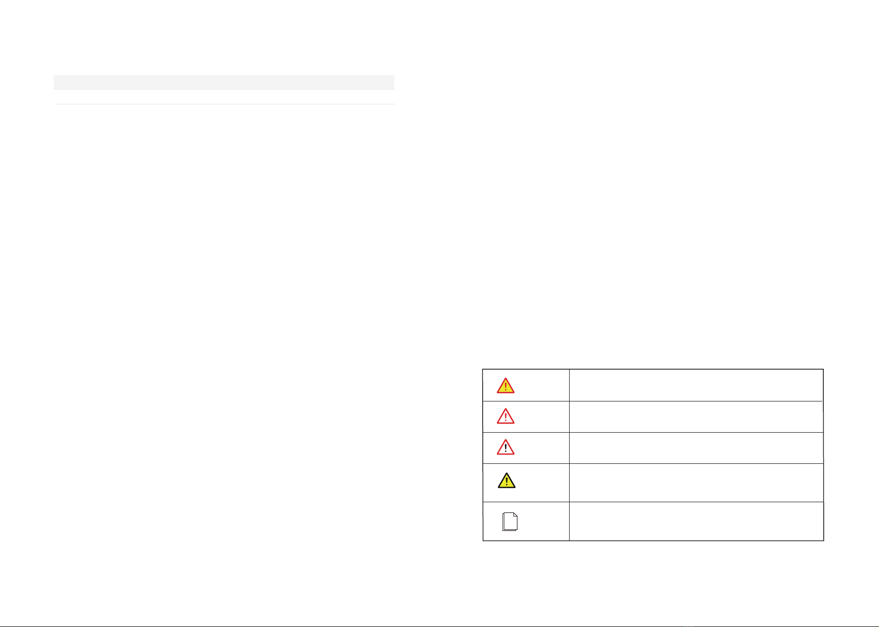
Indicates a potentially hazardous situation which, if not correctly
followed, will result in serious injury or death.
Indicates a potentially hazardous situation which, if not correctly
followed, could result in moderate or minor injury.
Indicates a potentially hazardous situation which, if not correctly
followed, could result in equipment failure to run, or property damage.
Call attention to important information, best practices and tips:
supplement additional safety instructions for your better use of the
inverter to reduce the waste of you resource.
VERSION ISSUED COMMENTS
1.0 11-Nov-22 First release
3
Conventions
Indicates an imminently hazardous situation which, if not correctly
followed, will result in serious injury or death.
Natural cooling series Fan cooling series Fan cooling series
5KTL-D3/G2
6KTL-D3/G2
8KTL-D3/G2
10KTL-D3/G2
10KTL-D3/G2P
12KTL-D3/G2
15KTL-D3/G2
12KTL-D3/G2P
15KTL-D3/G2P
17KTL-D3/G2
20KTL-D3/G2
22KTL-D3/G2
25KTL-D3/G2
30KTL-D3/G2
History
About This Manual
The following safety instructions and general information are used within this user manual.
This manual describes the installation, electrical connection, commissioning, maintenance, and APP
operation of the inverter. Please first read this manual and related documents carefully before using the
product and store it in a place where installation, operation and maintenance personnel can access it at
any time. The illustration in this user manual is for reference only. This user manual is subject to change
without prior notice.

CONTENTS
1. Safety
2. Product Introduction
3. Unpacking and Storage
4. Installation
5. Electrical Connection
About This Manual
Target Group
Scope
Conventions
1.1 Symbols Used
1.2 Safety Instruction
2.1 Product Overview
2.2 Model Definition
2.3 Product Appearance
3.1 Unpacking and Check
3.2 Storage Inverter
3.3 Identify Inverter
4.1 Selecting the Mounting Location
4.2 Mounting
5.1 Grounding
5.2 AC Connection
5.3 DC Connection
5.4 Communication Connection
6.1 Check before startup/shutdown procedure
6.2 Startup/Shutdown steps
6.3 Shutdown procedure
8.1 Inverter Troubleshooting
8.2 Maintenance
8.2.1 Routine Maintenance
8.2.2 Fan Maintenance
8.2.3 Removing the Inverter
5
4
Preface 6. Startup/Shutdown Procedure
7. User Interface
8. Troubleshooting and Maintenance
9. Technical Specifications

1. Safety
Before using the inverter, please read all instructions and cautionary markings on the unit and manual.
Put the instructions where you can take them easily.
The inverter of us strictly conforms to related safety rules in design and test. Local safety regulations
shall be followed during installation, operation and maintenance. Incorrect operation work may cause
injury or death and damage to the inverter and other operator or a third party.
To avoid injury and damage to the inverter and other operator,please follow the safety precautions.
7
6
Safety Safety
1.2 Safety Instruction
Installation and maintenance of inverters must be performed by qualified personnel, in accordance with
local electrical standards, wiring regulations and requirements of local power authorities.
The temperature of some parts of the inverter may exceed 60℃ during operation, do not touch the
inverter during operation to avoid being burnt.
Ensure children are kept away from inverters.
Take appropriate measures to avoid electric shock.
Don’t open the front cover of the inverter. Apart from performing work at the wiring terminal,
touching or changing components without authorization may cause injury to people, damage to
inverters and annulment of the warranty.
Ensure the output voltage of the proposed PV array is lower than the maximum rated input voltage of
the inverter; otherwise the inverter may be damaged and the warranty annulled.
When exposed to sunlight, the PV array generates dangerous high DC voltage. Please operate according
to our instructions, or it will result in danger to life.
Don’t insert or pull the terminals when the inverter is running.
After the inverter is powered off, the remaining electricity and heat may still cause electric shock and
body burns. Do not touch parts of inverter for 10 minutes after disconnection from the power sources.
Danger of high voltage!
Only qualified personnel may perform work on the inverter.
Grounding terminal
1.1 Symbols Used
Safety Symbol Description
Residual voltage exists after the inverter is powered off. It
takes 5 minutes for system to discharge to a safe voltage.
Danger of hot surface
Don’t dispose of the inverter with the household waste.
Do not disconnect under load!
5 mins
Environmental Protection Use Period
Refer to the operating instructions
The sign of caution stick on inverter.
Do not disconnect with load, otherwise there will be
danger of fire.

The three-phase grid-tied PV inverter converts the DC generated by PV panels into three-phase
alternating current and is delivered to the grid.
This series inverter is an important part of PV system and it is suitable for household use,
commercial use, fishery use, agricultural use and other scenarios.
2.1 Overview
2. Product Introduction 2.3 Product Appearance
PV strings Inverter AC Distribution Unit Grid
TN-S
L1
L2
L3
N
PE
PE
Transformer
TN-C
L1
L2
L3
PEN
PE
TN-C-S
L1
L2
L3
N
PE
PE
TT
L1
L2
L3
N
PE
PE
Transformer Transformer Transformer
The following is only for reference, specific please in kind prevail.
2.2 Model Definition
Model number descriptions (using 10KTL-D3/G2, 10KTL-D3/G2P as an example):
10KTL-D3/G2
Power(10KW)
Double MPPT; Three phase
Grid-tied;second generation
10KTL-D3/G2P
Power(10KW)
Double MPPT; Three phase
Grid-tied; second generation
Plus type
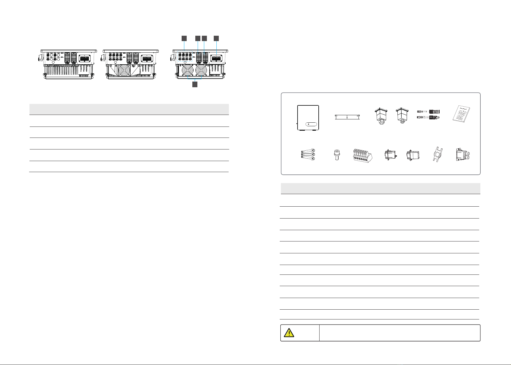
208.5mm 414.27mm
398mm
23
1
Number Description
1 DC Switch
2 LED Indicators
3 LCD Screen(Optional)
4 External ground terminal
Natural cooling series Fan cooling series
4
460mm
9
8
Product Introduction Product Introduction
190.5mm
480.5mm
Inverter Inverter Inverter Inverter
(Only take fan cooling as an example in appearance)
(Only take natural cooling as an example in appearance)
This series inverter is suitable for TN-S, TN-C, TN-C-S and TT grid system. Refer to the following figures:
9
10
Natural cooling series Fan cooling series 1 Fan cooling series 2
5 6 7 8
Number Description
5 PV terminal
6 RS485 communication port
7 WiFi/GPRS/LAN model communication port (Optional)
8 AC output port
9 External fan (It is only suitable for Fan cooling series)
Complete test and strict inspection shall be done before the inverter is sent out.
When receiving the inverter, check that the packing materials are intact.
After unpacking, examine the PV inverter and its fittings for damage and check that the deliverables
are complete.
3.1 Unpacking and Check
3. Unpacking and Storage
A B CDE
FGH I JK
Number Description Quantity
A The Inverter 1
B Bracket 1
C AC cover (with 4× M4 security screws) 1
D PV connectors 2 or 4
E File package 1
F Expansion screws groups 3
G M6 Security screw 2
H 6-Pin terminal 2
I WiFi/GPRS/LAN module (Optional) 1 (Optional)
JRemove tool for PV connector 1 (Optional)
KRS485 cover 1
11
Product Introduction Unpacking and Storage
NOTICE Contact your dealer immediately if there is any issue found during operation.
Or
Or

3.2 Storage Inverter
Number Description
1 Product name and model
2 Product technical parameters
3 SN Barcode
4 Approve and Safety identification
Ensure there is no electronical connections around ports of the PV inverter
before installation.
4. Installation
Product Name :
Product Model:
Max.Input Voltage:
Input Voltage Range :
Max.Input Current:
Input Short Circuit Current:
Rated Output Voltage :
Rated Output Frequency:
Max.Output Current :
Rated Output Power:
Max.Apparent Power:
Adjustable Power Factor Range:
Enclosure:
Temperature Range:
Protective Class:
1
2
3
4
DANGER
After checking the outer packing, move the PV inverter to the designated installation position horizontally.
CAUTION
1. Please place the inverter horizontally on the foam or other soft pads and
ensure that the ports are free of load-bearing pressure to avoid inverter
damages or scratches.
2. The inverter is heavy, be careful to prevent the inverter from slipping
and hurting the operator when moving the inverter.
4.1 Selecting the Mounting Location
a. The storage inverter protection class is IP65 and can be mounted indoors or outdoors.
b. To ensure optimum operation and long service life, the ambient temperature must be below 50℃.
c. Do not install the inverter in a rest area since it will cause noise during operation.
d.The inverter carrier must be fire-proof. Do not mount the inverter on flammable building materials.
e. Ensure that the wall meets the requirements of the inverter installation.
f . Product label and warning symbols shall be clear to read after installation.
g. The installation height should be reasonable and make sure it is easy to operate and view the display.
h. Please avoid direct sunlight, rain exposure, and snow cover.
4.1.1 Installation Environment Requirements
12 13
Installation
Unpacking and Storage
If the inverter is not used immediately, please keep the inverter in a specific environment according to the
following requirements:
Do not unpack the inverter and put desiccant in the original box if the PV inverter is unpacked.
Store temperature range: -25°C~+60°C; Relative humidity range: 0~100%.
Don’t position the inverter leaning forward, excessively leaning backward, tilting laterally, or upside down.
Ensure that qualified personnel inspect and test the inverter before use if it has been stored for a long time.
Inverter body label. The following is only for reference, specific please in kind prevail!
3.3 Identify Inverter
No direct sunlight No Rain Exposure No snow cover
Snow cover
Direct Sunlight Rain Exposure

Upright Lean back ≤15° Horizontally
Mount the inverter vertically or tilted backward by max 15°. In order to facilitate the heat dissipation of
the inverter.
≤15°
Upside-down
≥600
≥600
≥600
≥600
Above: 600mm
Below: 600mm
Front: 1000mm
Both sides: 600mm
Installation along the same line for multiple inverters
600mm 600mm
≥1000
NOTICE
4.1.3 Installation Space Requirements
4.1.2 Mounting Requirements
The wrong installation mode causes the inverter to be damaged or unable to
work properly.
To ensure the operation of the inverter normally and easily, there are requirements on available spaces
of the inverter, e.g. to keep enough clearance. Refer to the following figures.
14 15
Installation Installation
7
51
27
Installation perspective schematic
354
64
8
8
15
20
294
27
8
Bracket plane size drawing
Unit: mm
(Only take fan cooling as an example in appearance)
To prevent damage of the inverter, please hang the inverter on the bracket
and confirm the reverse, do not loosen the handle until the inverter is fixed.
CAUTION
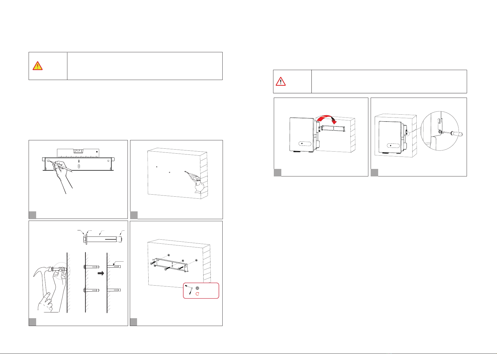
4.2 Mounting
DANGER
Step 1. Install the mounting bracket Step 2. Install the inverter.
Install the inverter on the bracket accurately and tighten the screws at both sides, as shown in Step 5 and
Step 6.
1.The walls must be fireproof and non-flammable materials, othewise there
is a fire risk.
2.Before drilling holes, check whether there are electric power pipes buried
in the walls to avoid risks.
(M6; 3 suites)
A B C D
Expansion screw group
Ø:10mm; Depth: 60mm
Set bracket horizontally.
Install bracket.
1
Mark the holes position on the wall.
2
Drill the holes.
3Install the expansion screw
4
5
6
2×M6 screw; 2 N·m
Tighten the screws at both sides.
Install the inverter.
16 17
Installation Installation
C & D
M6
2.5N·m
1 ) Use a level gauge to set braket horizontally, and then mark the position of the 3 holes on the wall.
Refer to Step 1. And drill 3 holes,10mm in diameter and 60 mm in depth. Refer to Step 1 and Step 2.
2) Knock the expansion screw kit into the hole together with a hammer. Refer to Step 3.
Note: Do not remove the nut unit.
3) After tightening 2-3 buckles, the expansion bolts are tight and not loose, and then unscrew the bolts,
spring washer, gasket. Refer to Step 3.
4) Install the bracket on the wall, the bracket screw is pointed at the expansion tube on the wall, then install
the gasket and tighten screw. Refer to Step 4.
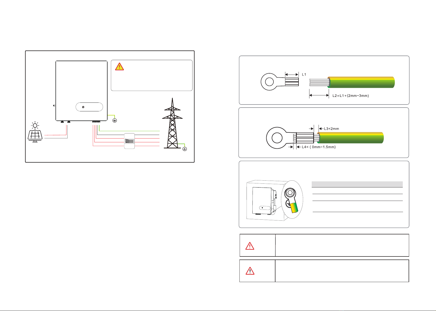
System Connection
CAUTION
According to regulations, the secondary protection grounding can’t replace
the PE terminal connection of the AC cable. Ensure that both are grounded
reliably. Otherwise, fatal injury can occur due to the high voltage.
WARNING
5. Electrical Connection 5.1 Grounding
Electrical Connection Electrical Connection
If the positive pole or negative pole of the PV array is required to be
grounded, then the inverter output (to AC grid) must be isolated by
transformer in accordance with IEC63109-1, -2 standards.
Step2.Insert the exposed core wires into the crimping areas of the OT terminal and crimp them
using hydraulic pliers.
Step3.Remove the ground screws from the ground points.
Step1.Remove an appropriate length using a wire Stripper.
According to the EN50178 requirement, the right side of the device has a protective grounding connection.
Be sure to connect the protection ground cable to this port when installing the inverter.
The user can perform the ground connection according to the on-site condition.
PE
DANGER
Before electrical connection, please ensure
that both the AC and DC ends are powered off,
otherwise there will be a high voltage shock.
Grid
L1L2L3 N PE
PE
N
L3
L2
L1
PE
PV+
PV-
18 19
Screw M6 × 12mm; 3 N·m
OT Terminal OT6-6(5K-15K); OT16-6(17K-30K)
Ensure that the grounding resistance is less than 10Ω.
Items Remark
Yellow green lines S(Yellow green lines) ≥ S(PE line of DC cable)
S is the cross-sectional area.
Other manuals for 5KTL-D3/G2
1
This manual suits for next models
13
Table of contents
Other Energy Inverter manuals


