
Energy Star SD44BNK5LS User manual

SD44 LED
CEILING FAN
MODEL #SD44BNK5LS
SD44LW5LS
SD44MBK5LS
SD44NWZ5LS
Purchase Date
1
Questions, problems, missing parts? Before returning to your retailer, call our customer
service department at 1-800-527-1292, 8:30 a.m. - 5 p.m., CST, Monday - Friday.
Español p. 20
ATTACH YOUR RECEIPT HERE
ADJUNTE SU RECIBO AQUÍ
ITEM #2742219
2742222
2742220
2742221
4007498

2
Safety Information .................................................................................................................
2
Package Contents .................................................................................................................
5
Hardware Contents ...............................................................................................................
6
Preparation ........................................................................................................................... 6
Initial Installation ................................................................................................................... 6
Downrod-Style Fan Mounting ............................................................................................... 8
Closemount-Style Fan Mounting ........................................................................................
10
Wiring .................................................................................................................................. 11
Final Installation ..................................................................................................................
13
Operating Instructions .........................................................................................................
16
Care and Maintenance ........................................................................................................
18
Troubleshooting .................................................................................................................. 18
Limited Lifetime Warranty ................................................................................................... 19
Replacement Parts List .....................................................................................................
..
19
TABLE OF CONTENTS
Modifications not approved by the party responsible for compliance could void the user's authority to
operate the equipment.
*NOTE: This equipment has been tested and found to comply with the limits for a Class B digital
device, pursuant to Part 15 of the FCC Rules. These limits are designed to provide reasonable
protection against harmful interference in a residential installation. This equipment generates,
uses and can radiate radio frequency energy and, if not installed and used in accordance with the
instructions, may cause harmful interference to radio communications. However, there is no guarantee
that interference will not occur in a particular installation. If this equipment does cause harmful
interference to radio or television reception, which can be determined by turning the equipment off and
on, the user is encouraged to try to correct the interference by one or more of the following measures:
* Reorient or relocate the receiving antenna.
* Increase the separation between the equipment and receiver.
* Connect the equipment into an outlet on a circuit different from that to which the
receiver is connected.
Consult the dealer or an experienced radio/TV technician for help.
Distributed by: Litex Industries Inc., P.O. Box 535639, Grand Prairie, TX, 75053; 1-800-527-1292
The device complies with Part 15 of the FCC Rules. Operation is subject to the following two
conditions: (1) this device may not cause harmful interference, (2) this device must accept any
interference received, including interference that may cause undesired operation.
NOTE: Dimmable to 10%.
SAFETY INFORMATION

READ AND SAVE THESE INSTRUCTIONS
Please read and understand this entire manual before attempting to assemble, install or operate the
product.
• Do not discard fan carton or foam inserts. Should this fan need to be returned to the factory for
repairs, it must be shipped in its original packaging to ensure proper protection against damage that
might exceed the initial cause for return.
• Make sure all electrical connections comply with local codes, ordinances, the National Electrical
Code and ANSI/NFPA 70-1999. Hire a qualified electrician or consult a do-it-yourself wiring
handbook if you are unfamiliar with installing electrical wiring.
• Make sure the installation site you choose allows a minimum clearance of 7 ft. from the blades to
the floor and at least 30 in. from the end of the blades to any obstruction.
• After you install the fan, make sure all connections are secure to prevent the fan from falling.
• The net weight of this fan including the light kit is: 16.28 lbs.
SAFETY INFORMATION
WARNING
To reduce the risk of fire, electrical shock or personal injury, mount fan to outlet box
marked "ACCEPTABLE FOR FAN SUPPORT OF 35 LBS. OR LESS" and use
mounting screws provided with the outlet box. Most outlet boxes commonly used for the
support of lighting fixtures are not acceptable for fan support and may need to be replaced.
Consult a qualified electrician if in doubt.
When mounting fan to a ceiling outlet box, use a METAL octagonal outlet box; do NOT use a
plastic outlet box. Secure the outlet box directly to the building structure. The outlet box and its
support must be able to support the moving weight of the fan (at least 35 lbs.).
To avoid personal injury, the use of gloves may be necessary while handling fan parts with sharp
edges.
To reduce the risk of fire, electrical shock or personal injury, wire connectors provided with this
fan are designed to accept only one 12-gauge house wire and two lead wires from the fan. If
your house wire is larger than 12-gauge or there is more than one house wire to connect to the
corresponding fan lead wires, consult an electrician for the proper size wire connectors to use.
WARNING
DANGER
When using an existing outlet box, make sure the outlet box is securely attached to the building
structure and can support the full weight of the fan. Failure to do this can result in serious injury or
death. The stability of the outlet box is essential in minimizing wobble and noise in the fan after
installation is complete.
To reduce the risk of serious bodily injury, DO NOT use power tools to assemble any part of the
fan, including the blades.
3

4
SAFETY INFORMATION
CAUTION
Read all instructions and safety information before installing your new fan. Review the
accompanying assembly diagrams.
Be sure outlet box is properly grounded and that a ground wire (green or bare) is present.
Once installation is complete, carefully check all screws, bolts and nuts on fan motor assembly to
ensure that they are secured.
Do NOT tamper with or attempt to repair LED component. The light source is designed for this
specific application and should not be serviced by untrained personnel. If any servicing is required,
call our customer service department.
WARNING
To reduce the risk of fire or electrical shock, do not use the fan with any solid state speed control
device or control fan speed with a full range dimmer switch.
To reduce the risk of fire, electrical shock or personal injury, do not bend the blade arms when
installing them, balancing the blades or cleaning the fan. Do not insert objects between the
rotating fan blades.
To reduce the risk of personal injury, use only parts provided with this fan. The use of parts
OTHER than those provided with this fan will void the warranty.
Before proceeding, be sure to shut off electricity at main switch or circuit breaker in order to
avoid electrical shock.
The DC Motor will not operate until blades are installed.
WARNING

K
PACKAGE CONTENTS
A
D
B
F
C
ML
J
I
5
E
O
P
Q
R
H
G
S
N
T
A Downrod 1
B Canopy 1
C Mounting Bracket 1
D Motor Housing 1
E Yoke Cover 1
F Light Kit Fitter 1
G Blade 5
H Blade Arm 5
I Shade 1
J Motor Screw/Lock Washer 10
(preassembled) + 1 extra
DESCRIPTIONPART QUANTITY DESCRIPTIONPART QUANTITY
K Canopy Mounting Screw 4
/Lock Washer
(preassembled)
L Pin (preassembled) 1
M Clip (preassembled) 1
N Rubber Washer 1
(preassembled)
O Hex Nut (preassembled) 1
P Flat Washer (preassembled) 1
Q Bulb 2
R Finial Plate (preassembled) 1
S Finial (preassembled) 1
T Switch Housing Screw 3
(preassembled)
IMPORTANT REMINDER: You must use the
parts provided with this fan for proper installation
and safety.

6
HARDWARE CONTENTS (shown actual size)
Before beginning assembly of product, make sure all parts are present. Place motor on carpet or on
foam to avoid damage to finish. Compare parts with package contents list and hardware contents list.
If any part is missing or damaged, do not attempt to assemble the product.
Estimated Assembly Time: 120 minutes
Tools Required for Assembly (not included): Electrical Tape, Phillips Screwdriver, Pliers, Safety
Glasses, Stepladder and Wire Strippers
Helpful Tools (not included): AC Tester Light, Tape Measure, Do-It-Yourself Wiring Handbook and
Wire Cutters
PREPARATION
Fiber
Blade
Washer
Qty. 15
+ 1 extra
CC
Blade
Screw
Qty. 15
+ 1 extra
Wire
Connector
Qty. 4
AA BB CC
INITIAL INSTALLATION
ON
OFF
ON
OFF
1
Turn off circuit breakers and wall switch to the fan
supply line leads.
DANGER: Failure to disconnect power supply
prior to installation may result in serious injury or
death.
1.
Pull Chain
Extension
Qty. 2
DD

INITIAL INSTALLATION
7
A
B
2
19° max.
30 in.
min.
G
3
2. Determine mounting method to use.
A. Downrod mount (standard or angled ceiling)
B. Closemount (standard ceiling only)
IMPORTANT: If using the angle mount, check to
make sure the ceiling angle is not steeper than 19°.
*Helpful Hint: Downrod-style mounting is best
suited for ceilings 8 ft. or higher. For taller ceilings
you may want to use a longer downrod (not
included). Angle-style mounting is best suited for
angled or vaulted ceilings. A longer downrod is
sometimes necessary to ensure proper blade
clearance. Closemount mounting is more suitable
for ceilings lower than 8 ft. high.
Check to make sure blades (G) will be at least 30
in. from any obstruction and at least 7 ft. above the
floor.
3.
4
Open End
C
C
Secure mounting bracket (C) to outlet box (not
included) using screws, spring washers and flat
washers provided with the outlet box.
*NOTE: It is very important you use the proper
hardware when installing the mounting bracket
(C) as this will support the fan.
IMPORTANT: If using the angle mount, make
sure open end of mounting bracket (C) is
installed facing the higher point of the ceiling, and
ensure the ceiling angle is not steeper than 19°.
4.
ANGLE
MOUNT
STANDARD
MOUNT
7 ft.
min.

INITIAL INSTALLATION
8
DOWNROD-STYLE FAN MOUNTING
J
5
D
Plastic Motor Block
5. Remove motor screws/lock washers (J) and
from underside of motor housing (D). [If there are
plastic motor blocks installed with the motor
screws/lock washers (J), discard the plastic
motor blocks.]
For DOWNROD-STYLE FAN MOUNTING,
proceed to step 1 below.
For CLOSEMOUNT-STYLE FAN MOUNTING,
skip to page 10.
Remove pin (L) and clip (M) from downrod (A).
Partially loosen preassembled set screws and
nuts in yoke at top of motor housing (D).
1a.
1b.
1a
M
D
L
A
Yoke
Set Screw
& Nut
Side View
A
2. 2
B
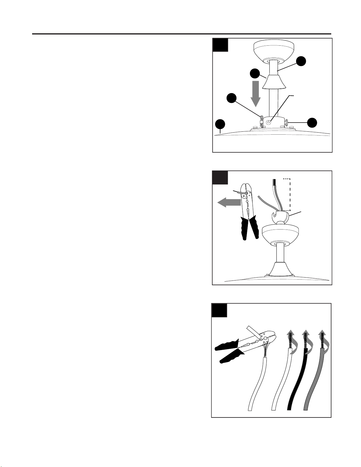
Insert downrod (A) through canopy (B) and yoke
cover (E). Thread wires from motor housing (D) up
through downrod (A).
E
1b
DOWNROD-STYLE FAN MOUNTING
9
4.
3. 3
A
M
L
Set Screw
and Nut
Depending on the length of downrod you use, you
may need to cut the lead wires back to simplify the
wiring. If you decide to cut back the lead wires, it is
suggested you do so in the following manner:
Take the lead wires and make sure you have
pulled them all the way through the top of the
downrod. Start at the TOP of the hanging ball on
the downrod and measure 8 in. of lead wire, and
then cut the excess wire off with wire cutters (not
included).
NOTE: If you do not cut back the lead wires,
Steps 4 and 5 are not necessary and you may
proceed to Step 6 instead.
Slip downrod (A) into yoke, align holes and
re-install pin (L) and clip (M). Tighten downrod (A)
set screws and then tighten nuts. Slide yoke cover
(E) down until it rests on top of motor housing (D).
D
4
Hanging
Ball
8 in.
5
5. If you cut back the lead wires in Step 4, strip 3/4 in.
of insulation from end of of each wire -- white,
black, green and blue (if applicable). Twist stripped
ends of each strand of wire within the insulation
with pliers (not included).
E

10
DOWNROD-STYLE FAN MOUNTING
6.
Remove preassembled canopy cover from bottom
of canopy (B). NOTE: To remove canopy cover
from canopy (B), twist canopy cover until the two
small protrusions on the inner lip of the canopy
cover align with the two notches on the bottom of
the canopy (B). Pull on canopy cover to remove.
NOTE: The downrod (A), yoke cover (E) and
canopy cover are not used in this type of
installation.
CLOSEMOUNT-STYLE FAN MOUNTING
1.
C
Slot
Tab
6
A
Install hanging ball of downrod (A) into opening of
mounting bracket (C). Align the slot in hanging ball
with the tab in mounting bracket (C).
DANGER: Failure to align slot in hanging ball
with the tab in mounting bracket (C) may result in
serious injury or death.
Continue to WIRING on page 11.
1
Canopy
Cover
B
Remove every other preassembled screw and
lock washer from top of motor housing (D).
2. 2
Screw
Lock Washer
D
This manual suits for next models
7
Table of contents
Other Energy Star Fan manuals


Popular Fan manuals by other brands

ELTA FANS
ELTA FANS H03VV-F installation guide

Hunter
Hunter 20714 Owner's guide and installation manual

Emerson
Emerson CARRERA VERANDA CF542ORB00 owner's manual

Hunter
Hunter Caraway Owner's guide and installation manual

Panasonic
Panasonic FV-15NLFS1 Service manual

Kompernass
Kompernass KH 1150 operating instructions




