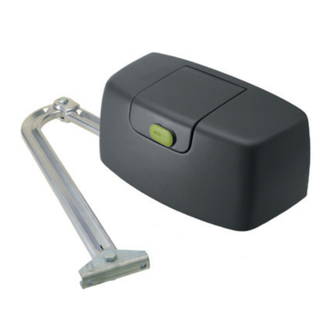
Elsema iS900Solar24 User manual

1
AXIOM SLIDING GATE KIT USER MANUAL
iS900Solar24
SLIDING GATE OPENER
USER MANUAL
Bluetooth charge monitoring app

2
AXIOM SLIDING GATE KIT USER MANUAL
Safety Instructions
Save these instructions for future reference.
WARNING! FAILURE TO FOLLOW THESE SAFETY AND INSTALLATION INSTRUCTIONS
COULD RESULT IN INJURY OR DEATH AND
/
OR DAMAGE TO PROPERTY AND EQUIPMENT
.
Appropriately licensed and competent personnel only should install the automation equipment.
The operators are designed specifically to open and close sliding gates or doors and should not be used for any
other purpose.
The gate can operate unexpectedly, so ensure nothing remains in its path.
Do not
operate the gate unless the user has a full view of the gate and there are no objects, person/children in the
gate operation area.
Do not
let children play with the transmitters or any other gate control system.
Do not disengage
the gate opener to manual when there are children, people, objects, or vehicles within the
gate’s operation area. Manual release may cause uncontrolled movement.
Always incorporate the appropriate Photo Electric Beams, Safety Bump Strip, Induction Loops and other
safety devices to protect both equipment and personnel. Monitored Photoelectric Beam must be installed
and operational.
Display all necessary signs to indicate any danger areas and automatic operation of the gate or door.
The operators are not designed to be used in any hazardous areas or areas subject to flooding etc.
All electrical connections and wiring must be performed with AS/NZS 3000-2018 as the guidelines.
The manufacturer of the automation equipment is not responsible for the damage which may be caused to either
the operator, gate or door and any other person or equipment when: -
oWrong or poor installation practices were performed.
oNo or inadequate safety devices were used.
oPoor maintenance on the equipment.
oAny other circumstances beyond the manufacturers control.
oAutomated gates must comply to AS/NZS 60335.1 in conjunction with AS/NZS 60335.2.103.
WARNING!
ELECTRICITY CAN KILL
Isolate power
before attempting any maintenance.
Only qualified personnel
should carry out maintenance.
The installer
should provide all information concerning the use of the automation equipment as well as
instructions regarding the manual override and maintenance procedures to the users of the system.
Keep loose clothing and hands away from the gate whilst its being operated or could possibly be operated!
Inspect the gate or door, along with its supporting posts and walls, to guard against potential shearing,
compression, and other hazards that could lead to severe
injuries or fatalities
.
Check the gateposts or mounting structure has the necessary strength and rigidity to support the operator and the
load of the opening and closing gate motion.
The product comes with wireless transmitters equipped with coin/button cell batteries,
which are hazardous. Ensure these devices and their batteries are kept out of reach of
children. If the battery is swallowed, it can cause severe internal burns and can lead to
death in as little as 2 hours. Always secure the battery compartment. If you suspect that
battery has been swallowed or inserted into any part of the body, SEEK MEDICAL HELP
IMMEDIATELY.
Battery warning!

3
AXIOM SLIDING GATE KIT USER MANUAL
Kit Contents
1
Sliding gate motor with Smart solar controller and Li-ion Battery
pack
2
3 x PentaFOB®Remotes
3
Fastener Pack
4
Motor base plate
5
4 x Gear rack kit with mounting screws
GR-4
6
Long range reflector type photo electric beam. PE-1500
7
1 x 24 Volt, 40W Solar panel
670 x 570 x 35 mm

4
AXIOM SLIDING GATE KIT USER MANUAL
Dimensions

5
AXIOM SLIDING GATE KIT USER MANUAL
TECHNICAL FEATURES:
Installation
A. CHECKS BEFORE INSTALLATION
Before proceeding with the installation check the following:
1. The structure of the gate should be suitable for automation.
2. The gate should be supported by upper guides.
3. Mechanical end stoppers must be provided to prevent the gate from running off the track.
4. The foundation should be strong enough to support the operator.
5. There are no cables or pipes in the path of the operator and the gate.
6. Be sure that gate moves freely.
7. There are no obstacles in the moving gate area.
8. The operator is not in a position where it can be easily or accidently damaged by passing
vehicles.
9. The 2 x limit magnets should have different marking on them. One should have a and the
other should have a .You cannot use the limit magnets if they have the same marking. The
magnets can be installed on either side (open or close). Please see the diagram below to locate
the marking on the magnets.
iS900Solar24
Motor
V
oltage
24Volts DC motor
Max Absorbed Power 120 Watts
Nominal Thrust 330N
Power Supply 240 Volts AC
Nominal Input Current 3 Amps
Motor Speed 250 mm/sec
Maximum Gate Weight 900 kg
Duty Cycle 60% over 12 min
Operating Temperature -20°c - +50°c
Solar Panel 670 x 570 x 35 mm
Gate Weight Up to 900Kg on level ground

6
AXIOM SLIDING GATE KIT USER MANUAL
B. INSTALLATION WITH CONCRETE
Assemble the base plate bracket as shown in fig 1.
Fig 1
Run Conduit and power cables, accessories and sensor cables through the slot in the base
plate before pouring concrete. Make sure you have enough length on the cable to wire into
the control card.
While pouring the concrete, make sure that the base plate is level horizontally and straight
with respect to the gate.
After pouring concrete, make sure that the threaded part of the anchor TruBolts are clean.
Do not work on it until the concrete is hard.

7
AXIOM SLIDING GATE KIT USER MANUAL
C. INSTALLATION ON EXISTING FOUNDATION
Use TruBolts included in the kit to secure the base plate on solid concrete surface. Making sure that
the distance from both edges of the base plate to the gate should be the same. Excess length of the
TruBolt will need to be cut.
D. Mount the operator on to the base plate with the screws provided as shown below.

8
AXIOM SLIDING GATE KIT USER MANUAL
E. GEAR RACK INSTALLATION
1. Move the Gate leaf to fully closed position.
2. Place the first piece of the rack over the pinion leaving about 1.5mm gap and mark the
drilling point on the gate, drill a pilot hole and screw the rack using the self-tapping screw
with the reinforcing plate.
3. Move the gate manually, making sure that the rack is resting on the pinion and fix all
other screws.
4. Bring the next rack and join it to the previous one by slotting it into inter-connecting slots.
5. Repeat this process until the gate is fully covered from fully open to fully close positions.
F. CHECK GEAR RACK INSTALLATION
Make sure that the rack is constantly in full contact with the pinion for the full open and
close travel cycle.
Manually check if the gate reaches the mechanical stop limits and make sure there is no
friction during gate travel.
Do not use grease or other lubricants between rack and pinion

9
AXIOM SLIDING GATE KIT USER MANUAL
G. LIMIT SWITCH ADJUSTMENT
Install the limit switch magnets as shown in fig 6.
The limit switch magnets should be initially installed at least 50mm before the end of travel
on both sides. Final adjustment should be done after successful travel learning with the
control card.
Adjustments of the limit switch should be done after all other components are installed
securely.
Fig 6
When steel gear rack is used (or gear rack which are much slimmer), you will have to use the
packing block which comes with the limit switches. Please see the diagram below

10
AXIOM SLIDING GATE KIT USER MANUAL
H. Manual Release
The operator has an unlocking mechanism. Once it’s unlocked, the gate can be operated manually
in both directions. The unlocking key is needed to unlock the motor. Please keep the key in a safe
place for later use. The manual release lever is located towards the bottom of the operator. (See
pictures below). Use the key to unlock the manual release lever. Once unlocked pull the lever so
that it’s perpendicular to the motor. The gate can now be used manually.
I. ELECTRICAL CONNECTION
After successful motor installation, refer to the user manual of the control card
for automatic operation setup.
J. SOLAR CHARGE MONITORING APP*
Once the gate is fully commissioned and operational, the solar charging monitoring app can be
downloaded from the app store. This app will show the user the battery status in real time,
charging current, battery voltage and the output of the solar panel. To download the app, go to
the app store and search for VictronConnect.
*Do not change any setting of the solar controller. It has already been optimised for the Li-
ion battery. Any changes will void the warranty and can cause damage to the battery and
the solar changer.
Table of contents
Other Elsema Gate Opener manuals

Elsema
Elsema Intelligent Swing iS330 User manual

Elsema
Elsema INTELLIGENT SLIDER iS1500LV User manual

Elsema
Elsema iS320 User manual

Elsema
Elsema iS270 User manual

Elsema
Elsema iS300 User manual

Elsema
Elsema iS500 series User manual

Elsema
Elsema iS1500 User manual

Elsema
Elsema iS2000 User manual

Elsema
Elsema iS250 User manual

Elsema
Elsema Eclipse MCS Manual