Elliott Roto-Jet 0420 Manual

www.elliott-tool.com
Tube & Pipe Cleaners Tube Testers Tube Plugs Tube Removal Tube Installation
0420 Roto-Jet™Cleaning System
Operating and Maintenance Instructions


0420 Roto-Jet 3
Table Of Contents
Introduction .......................................................................................................... 4
Safety ................................................................................................................... 5
Operation.............................................................................................................. 7
Operating Position (Diagram A)............................................................................ 8
Drive Coupling (Diagram B) ................................................................................ 10
Air Supply Requirements.................................................................................... 12
Maintenance....................................................................................................... 13
Technical Data .................................................................................................... 15
Trouble Shooting Guide...................................................................................... 17
Records ...................................................................................................... 20 & 21
Flexshaft Repair ................................................................................................. 24

4 0420 Roto-Jet
INTRODUCTION
Thank you for purchasing this Elliott product. More than 100 years of experience have been employed
in the design and manufacture of this control, representing the highest standard of quality, value and
durability. Elliott tools have proven themselves in thousands of hours of trouble free eld operation.
If this is your rst Elliott purchase, welcome to our company; our products are our ambassadors. If
this is a repeat purchase, you can rest assured that the same value you have received in the past will
continue with all of your purchases, now and in the future.
The Elliott Roto-Jet has been designed for cleaning tubes in the following types of equipment:
Heat Exchangers
Condensers
Chillers
If you have any questions regarding this product, manual or operating instructions, please call Elliott at
+1 800 332 0447 toll free (USA only) or +1 937 253 6133, or fax us at +1 937 253 9189 for immediate
service.

0420 Roto-Jet 5
SAFETY
Read and save all instructions. Before use, be sure everyone using this machine reads and under-
stands this manual, as well as any labels packaged with or attached to the machine.
1. Know Your Elliott Roto-Jet™. Read this manual carefully to learn your tool’s applications and
limitations, as well as potential hazards, associated with this type of equipment.
2. Keep Work Area Clean and Well Lighted. Cluttered, dark work areas invite accidents.
3. Dress Properly. Do not wear loose clothing or jewelry. Wear a protective hair covering to contain long
hair. It is recommended that the operator wear safety glasses with side shields or a full face shield eye
protection. Gloves and water repellant, nonskid footwear are also recommended. Keep hands and
gloves away from moving parts.
4. Use Safety Equipment. Everyone in the work area should wear safety goggles or glasses with side
shields complying with current safety standards. Wear hearing protection during extended use,
respirator for a conned space and a dust mask for dusty operations. Hard hats, face shields, safety
shoes, respirators, etc. should be used when specied or necessary.
5. Keep Bystanders Away. Bystanders should be kept at a safe distance from the work area to avoid
distracting the operator and contacting the exshafting or machine. Only the operator of the machine
should engage the foot switch control. NEVER PLACE A WEIGHTED OBJECT ON THE FOOT SWITCH
TO PRODUCE CONTINUOUS OPERATION OF THE MACHINE.
6. Protect Others in the Work Area from debris such as water exhaust and water spray. Provide barriers
or shields as needed.
7. Use the Right Cleaning Device. Do not use a cleaning device or attachment to do a job for which it
is not recommended. Refer to the Elliott E-100 catalog for all optional equipment. Do not alter the
machine or cleaning device, this will void the warranty on the product.
8. Use Proper Accessories. Use Elliott accessories only. Be sure accessories are properly installed and
maintained. Do not defeat a guard or other safety device when installing an accessory or attachment.
9. Check for Damaged Parts. Inspect guards and other parts before use. Check for misalignment,
binding of moving parts, improper mounting, broken parts or any other conditions that may affect
operation. If abnormal noise or vibration occurs, turn the machine off immediately and have the
problem corrected before further use. Do not use a damaged machine. Tag damaged machines “Do
Not Use” until repaired. A guard or other damaged part should be properly repaired or replaced by an
Elliott service facility. For all repairs, insist on only identical replacement parts.
10. Remove All Wrenches. Check that all accessory wrenches are removed from the system before
turning it on.
11. Avoid Accidental Starting. Be sure your machine is turned off before supplying air pressure. Do not
use a machine if the foot control switch is not turning the machine on and off. NEVER USE ANY
OBJECT TO HOLD THE FOOT SWITCH IN THE “ON” POSITION.
12. Do Not Force the Flexshaft. Your Elliott Roto-JetTM will perform best at the rate for which it was
designed. Excessive force only causes operator fatigue, increased exshaft wear, shaft or break-away
coupling failure.
13. Keep Hands Away from All Moving Parts.
14. Do Not Overreach - Maintain Control. Keep proper footing and balance at all times.

6 0420 Roto-Jet
15. Stay Alert. Watch what you are doing, and use common sense. DO NOT use a machine when you
are tired, distracted or under the inuence of drugs, alcohol or any medication causing decreased
control.
16. Remove the Air Supply to the Machine when it is not in use, before changing accessories or when
performing recommended maintenance.
17. Maintain Machine Carefully. Keep handles dry, clean and free from oil and grease. Follow
instructions for lubricating and changing accessories. For more information see “Maintenance”
section. Periodically inspect the machine and air supply hose for damage. Have damaged parts
repaired or replace by an Elliott service facility.
18. Store Idle Machines. When not is use, store your machine in a dry, heated, secured place. For more
information see “Maintenance” section.
19. Maintain Labels and Nameplates. These carry important information and will assist you in ordering
spare and replacement parts. If unreadable or missing, contact an Elliott service facility for a
replacement.
20. Stop the Machine Immediately if the Flexshaft Starts to Coil. Flexshaft damage will occur if exshaft
is operated in a coiled position.
21. Use the Proper Flexshaft to t the tubes to be cleaned. Never use a exshaft that is too small or
too short. Flexshaft failure will result if too great a resistance is placed on the exshaft. Refer to the
chart below for sizing information. (See Fig. 1 and 2)
Wet Shafts (Fig.1)
Prex Part Number Casing Outside Diameter Tube Inside Diameter
inch mm inch mm
0511*(xx) .250 6 5/16 - 3/8 8 - 10
0512*(xx) .375 10 7/16 - 1/2 11 - 13
0513*(xx) .500 13 9/16 - 1 14 - 25
0514A*(xx) .625 16 3/4 - 1-1/2 19 - 38
0514*(xx) .750 19 1 - 2 25 - 50
0515*(xx) 1.000 25 2 and over 50 and over
*Length of shaft in feet completes the part number.
(Available in standard lengths of 16’, 25’, 33’, and 49’. Consult factory for additional lengths.)
Dry Shafts (Fig.2)
Prex Part Number Casing Outside Diameter Tube Inside Diameter
inch mm inch mm
0534*(xx) 7/8 22 1 and over 25 and over
*Length of shaft in feet completes the part number.
(Available in standard lengths of 25’, 35’, and 50’. Consult factory for additional lengths.)
0420 Roto-Jet 7
OPERATION
Correct Machine Position and Operation is critical to getting the job done quickly and efciently.
This can be accomplished by the following these steps:
Examine the tubes to be cleaned and measure the internal diameter (Elliott Tube Gauge is
recommended) and length of the tubes. If the tube ends are expanded, then make a note of the
smallest internal diameter. Record these measurements on the chart provided in the back of
this manual. You will need these measurements to select the proper size exshaft and cleaning
attachments.
Carry the machine to the location where the cleaning will take place.
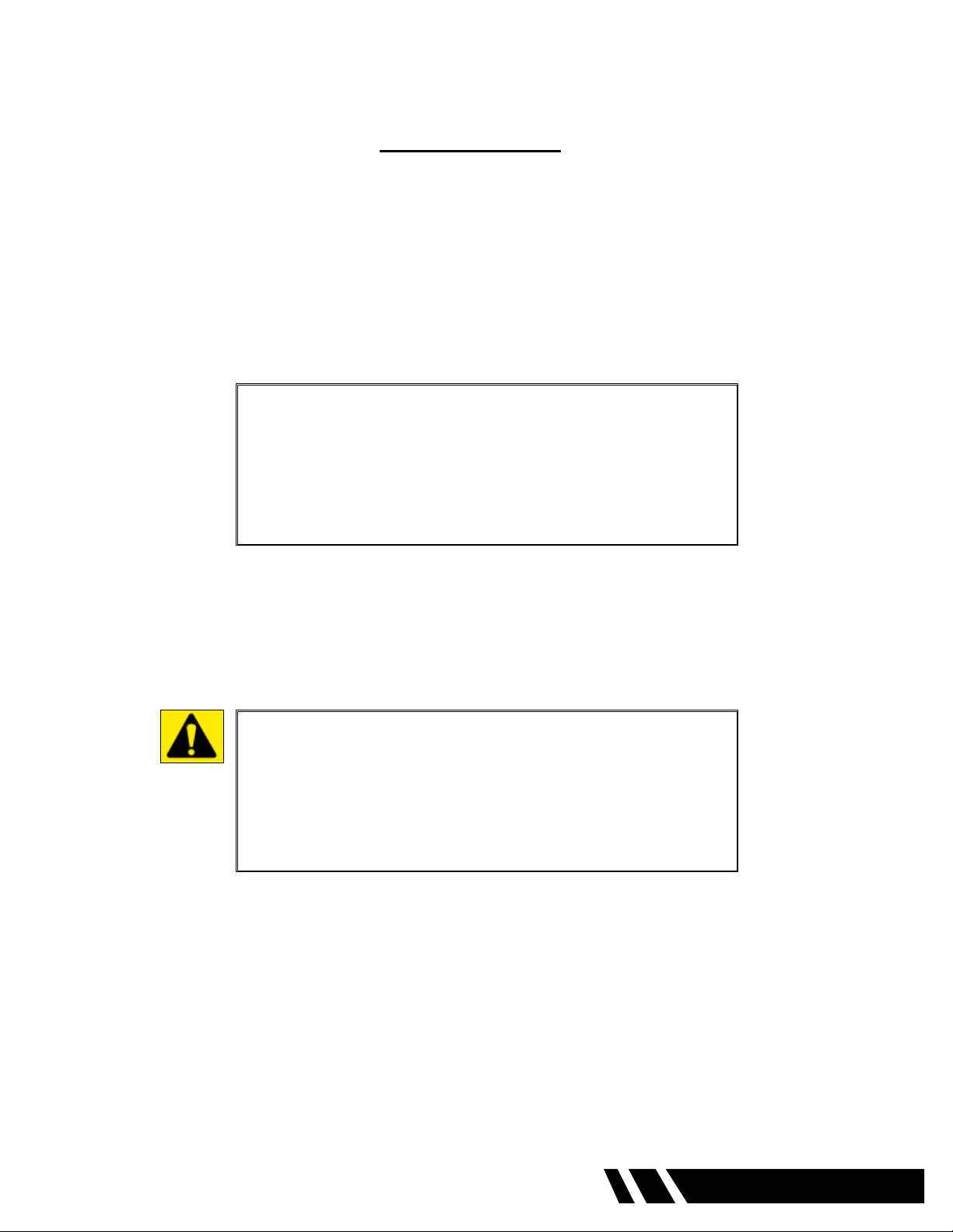
Position the machine at a right angle to the tube sheet or cleaning area. This will keep the exshaft
at the proper radius. NEVER OPERATE THE MACHINE IN THE VERTICAL POSITION.
(See Diagram A).
TOOL TIP
Always select a smaller size of cleaning device for heavy
tube deposits. With the exception of the Elliott Turbo Brush,
never use a brush or cleaning device larger than the internal
diameter of the tubes.
WARNING
This machine requires oil lubrication mixed with the air
supply. When using the machine in a conned space,
the operator must wear proper eye protection and use a
breathing apparatus capable of ltering airborne oil particles.
8 0420 Roto-Jet
DIAGRAM A
Tube Bundle
Roto-Jet
TOP VIEW
CORRECT OPERATING POSITION

0420 Roto-Jet 9
OPERATION (CONT.)
Open the foot switch storage compartment and remove the foot switch, “O” ring, rubber hose washer
and the air hose “quick disconnect” tting.
Position the foot switch hose in the cutout provided before closing compartment lid.
Install the quick disconnect to an air hose capable of withstanding 100 psi (6.89 Bar-Metric).
The hose should have an inside diameter of 1/2” (13mm).
Place the rubber hose washer in the water hose connection of the machine. This is a one time
operation. The rubber washer can remain in this connection and does not require removal after use.
Connect a standard garden hose to the 3/4” water hose connection of the machine. The machine is
designed for “Municipal” water pressure only, Max 100 psi (6.89 Bar-Metric). DO NOT connect the
water connection to a “High Pressure” source. Water is important to the cleaning process as it ushes
away deposits cleaned from the tube and helps to lubricate and cool the exshaft.
Position the “O” ring in the recess of the exshaft connection manifold.
Prepare the exshaft by loosening the four (4) set screws located in the brass locking sleeve using
a 3/32” Allen wrench. Thread the breakaway or solid square drive into the coupling adapter that
is swaged on the core of the exshaft. Position the brass locking sleeve equally over the coupling
adapter and the breakaway or solid square drive. Firmly tighten the four (4) Allen set screws. (See
Diagram B page 8)
Insert the square drive into the manifold of the machine. Rotate the exshaft by hand to properly seat
the square drive of the exshaft into the manifold. Thread the brass manifold cap onto the manifold of
the machine and rmly hand tighten.
Attach the chosen cleaning device to the tool coupling swaged to the core of the exshaft at the
opposite end from the manifold connection and rmly tighten the device. Connect the appropriate air
pressure source to the machine. For more information see “Air Supply” section.
Turn on the water supply.
Layout the exshaft as straight as possible. DO NOT start the machine with the exshaft in a coiled
position.
Depress the foot switch. Move the throttle valve located next to the air supply connection slowly until
the air motor starts to turn the exshaft. Adjust this valve to the desired RPM for the cleaning device
and exshaft being used. At the same time, water will pass through the machine and out the end of
the exshaft casing near the cleaning device. Remove your foot from the foot switch and both the
water and rotation of the shaft will stop. Restart the machine and observe the water output from the
end of the exshaft casing. A constant stream of water should be discharged from the casing as the
core rotates. If no water is discharged from the exshaft, check the hose and hose connection for any
“kinks” that would restrict water ow. Depress the foot switch again and observe the water ow from
the end of the exshaft. If no water is discharged, discontinue use of the machine and contact an
Elliott service facility.
10 0420 Roto-Jet
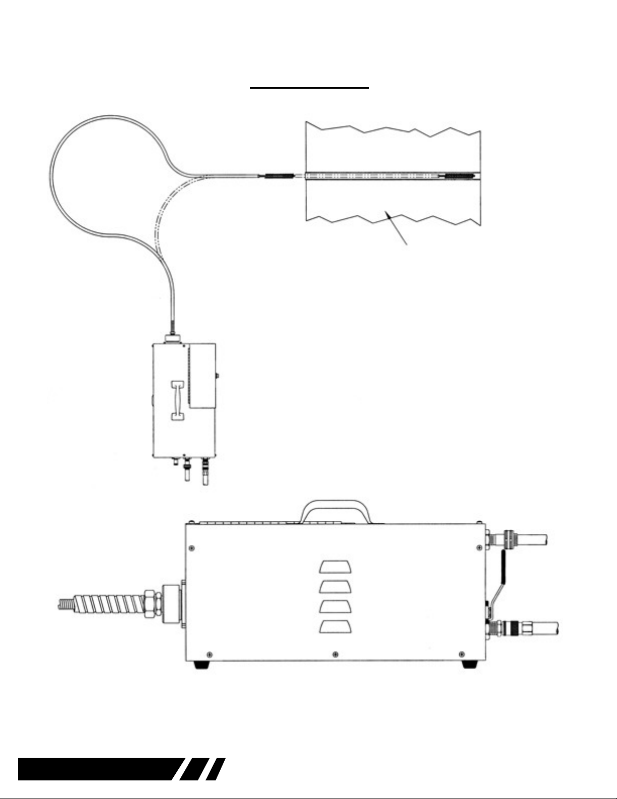
DIAGRAM B
TOOL TIP
Operate the exshaft as straight as possible to minimize any sharp radius
bends. This applies to both brush insertion and at maximum cleaning
length. Operating the exshaft in a constant sharp radius will ex fatigue
the wires in the core reducing its strength. Allowing the cleaning device
to exit the tube while rotating can cause premature shaft failure in the
tool coupling area. Never exit the tube with the tube cleaning device in
operation. For more information see “Technical” section.
TOOL TIP
Measure the length of the tubes being cleaned from the tube sheet to the tube
sheet at the opposite end. Transfer this measurement to the exshaft from
the END of the cleaning device up the casing toward the machine. Mark the
end of the measurement on the casing by wrapping the point with electrical
tape. This will enable you to feed the exshaft through the tube and stop the
cleaning device before exiting the tube on the opposite end.
TOOL TIP
Start to clean the tube bundle from the top of the unit to the bottom. Clean
the bundle one row at a time, marking with soapstone, each row of tubes that
have been cleaned.
Manifold Cap
Brass Coupling
Drive Coupling
Table of contents
Other Elliott Other manuals


