
ElectroHeat ECO-V 5 User manual

www.waterco.com.au
Installation and
Operation Manual
This equipment must be installed and serviced by a qualified technician.
Improper installation can create electrical hazards which could result in property
damage, serious injury or death. Improper installation will void the warranty.
Notice to Installer
This manual contains important information about the installation, operation and
safe use of this product. Once the product has been installed this manual must
be given to the owner/operator of this equipment.
WARNING
!
5, 9, 12, 17 kW
WATERCO POOL HEAT PUMP

Contents
Table of
• English
IMPORTANT SAFETY INSTRUCTIONS 02
A NOTE TO YOU 03
INSTALLATION INSTRUCTIONS 05
Location 05
Installation Clearances 06
Water Piping 07
Water Flow Rate 07
Water By-pass Kit 07
Plumbing Diagram 08
Electrical 09
Electrical Connection 09
Breaker Size 09
Electrical Wire Size 09
Bonding 10
Bonding Diagram 10
Remote Control Connections 11
Usage Of Chemical Products 12
Refrigerant Charge Indicator Gauge 12
Performance Specifications 13
OPERATION OF YOUR POOL HEAT PUMP 14
Initial Heating 14
Adjustment Of The Bypass Valves 14
Pool Heat Pump Running Time 15
Pool Solar Blanket 15
Defrost Cycle 15
INVERTER POOL HEAT PUMP CONTROLLER 16
Illustration for LCD Display 17
ON/OFF 17
Working modes 17
Water Temperature Setting 17
Operation Modes 17
Memory Function 18
MAINTENANCE OF YOUR POOL HEAT PUMP 19
Cabinet Cleaning 19
Cleaning Evaporator 19
Cleaning drainage holes 19
Units Located In Coastal Locations 19
Winterising Procedure 20
GENERAL SAFETY INSTRUCTIONS 21
TROUBLESHOOTING 22
Nothing Is Working and The Electronic
Control Does Not Operate 22
Nothing Is Working But The Electronic Control
Temperature Displays Digits or a Code 22
Fan Doesn’t Work (The Fan Blades
Are Not Moving) 22
Fan Blades Turn, But Compressor Is Not
Functioning 23
Compressor Starts and Stops 23
There Is Water Around The Pool Heat Pump 23
Pool Heat Pump Has Ice Formed On The
Evaporator Coil 24
Pool Heat Pump Is Functioning, But Does Not
Reach The Desired Temperature Setting 24
Circuit Breaker Trips 25
The Pool Heat Pump Is Noisy 25
The Temperature Shown On Pool Heat Pump
Is Not The Same That Is Shown By The Pool
Thermometer 25
Dimensional drawing of heat pump 26
Electric Circuit Drawing 27
Service Parameters Tables 30
Internal parameters 31
WARRANTY 33

IMPORTANT SAFETY INSTRUCTIONS
When using this electrical equipment, basic safety precautions should always be
followed, including the following:
READ AND FOLLOW ALL INSTRUCTIONS
! WARNING: Disconnect all AC power during installation and servicing.
! WARNING: In order to avoid the possibility of hyperthermia (heat stress) occurring
it is recommended the average temperature of the spa - pool water does not exceed
40°C / 104°F.
! WARNING: The pool heat pump is not intended for use by persons (including
children) with reduced physical sensory or mental capabilities, or lack of experience
and knowledge, unless they have been provided supervision or instruction concerning
use of the appliance by a person responsible for their safety. Children should be
supervised to ensure they do not play with the appliance.
• In certain situations unexpected start up may occur when the appliance is in automatic
mode.
• The installer should assess the risk associated with unexpected start-up of this device
which, in any circumstance should have no hazardous effect.
• The pool heat pump is not meant to provide safety protection for other devices.
• The pool heat pump should be deactivated if the pool or spa has been drained.
• Waterco pool heat pumps must be installed by a suitably qualified person in accordance
with current Regulatory Standards, the applicable Wiring Rules (AS3000) and local
statutory authority regulations.
• Parts containing live parts, except parts supplied with safety extra-low voltage not
exceeding 12V, must be inaccessible to a person in the spa – pool.
• Parts incorporating electrical components, except remote control devices, must be
located or fixed so that they cannot fall into the spa – pool.
• The appliance should be supplied through a residual current device (RCD) having a
rated residual operating current not exceeding 30mA.
• An Earth terminal is located inside the wiring enclosure. To reduce the risk of electric
shock, this terminal must be connected to the grounding means provided in the
electric supply service panel with a continuous copper wire as sized to comply with
current Standards and local statutory authorities in relation to the circuit conductors
supplying the equipment.
• A cable connector is provided on this unit to connect a suitably sized copper conductor
between this unit and any metal equipment, metal enclosures of electrical equipment,
metal water pipe, or conduit within 1.5m of the unit via equipotential bonding.
SAVE THESE INSTRUCTIONS.
Pool Heat Pump I 02

A NOTE TO YOU
Congratulations!
Thank you for choosing a Waterco Electroheat ECO-V inverter heat pump to heat
your pool.
Using the latest technology in heat capture, the Waterco pool heat pump converts
the energy released by the sun and transfers it efficiently to your swimming pool.
During certain periods it may be necessary to operate your pool heat pump
continuously during the day in cooler periods however, this should not be of concern
as your Waterco pool heat pump can heat up your pool approximately 80% more
economically than the fossil fuel heating or heaters with electric elements. Waterco
pool heat pumps are designed specifically to heat or cool your swimming pool
economically.
To appreciate the benefits this product will bring you, make sure to operate the unit
when the atmospheric conditions specified in this document are present in addition
of using a solar blanket to minimize heat loss which will influence operating costs and
size of the unit required. Pools not covered with a solar blanket lose 2 to 3 times more
heat, regardless of types of heating!
This manual applied to the following models:
Electroheat ECO - V inverter 5kW heat / cool with auto evaporator deicing
Electroheat ECO - V inverter 9kW heat / cool with auto evaporator deicing
Electroheat ECO - V inverter 12kW heat / cool with auto evaporator deicing
Electroheat ECO - V inverter 17kW heat / cool with auto evaporator deicing
Transportation and Storage
1. The heat pump MUST be transported and stored VERTICALLY!
2. The heat pump MUST be transported and stored uprightly on a pallet with good
package.
3. Should the heat pump be laid down, please wait at least 12 hours before switching
it on.
03 I Pool Heat Pump

Record your model’s information.
Keep this manual and your original proof of purchase receipt for warranty and
future reference.
On the base of your pool heat pump is a name plate which contains information such
as model number, serial number and electrical information.
Please write these down below and have them handy incase of a service call request.
Model Number ______________________________________________________
Serial Number ______________________________________________________
Purchase Date ______________________________________________________
Dealer Name ______________________________________________________
Dealer Address ______________________________________________________
Dealer Phone ______________________________________________________
To find detailed product information, the location of the nearest dealer or to register
your pool heat pump please visit our website www.waterco.com and select your
location.
Pool Heat Pump I 04

05 I Pool Heat Pump
INSTALLATION INSTRUCTIONS
Location
To gain maximum efficiency for your pool heat pump please follow all instructions
when “positioning the unit”. It is also important to allow clearances for future service
and maintenance procedures.
The unit is designed for outdoor installation and should not be installed in a totally
enclosed area such as a shed, garage, etc., unless ducted and fan assisted ventilation
of the cold exhaust air is provided to ensure adequate air exchange for correct
operation.
The unit shall be sited in a well ventilated area in order to avoid trapped cold discharge
air. Re-circulation of cold discharged air back into the evaporator coil should be
avoided and will greatly reduce unit’s heating capacity and efficiency.
The unit should be located as close as practically possible to the existing pool pump
and filter to minimize water piping. The use of 90 degree bends and short radius
elbows in the water piping should be kept to a minimum.
Mount the unit on a sturdy base, preferably a concrete slab or blocks arranged to
support the whole length of the unit. The base should be completely isolated from
the building foundation or wall to prevent the possibility of sound or vibration
transmission into the building. The size of the base should not be less than the base
of the pool heat pump.
Use of anti vibration mat between the base of the unit and final installation location
material is highly recommended to reduce potential vibration noise issues.
Fitting the two supplied drainage spigots to the rear of the base must be installed
prior to final installation of the unit.
The unit should be maneuvered into its final position and the anti vibration mounts
(supplied by installer) fitted under each foot.
Pool Heat Pump I 06
Figure 1
Installation Clearances
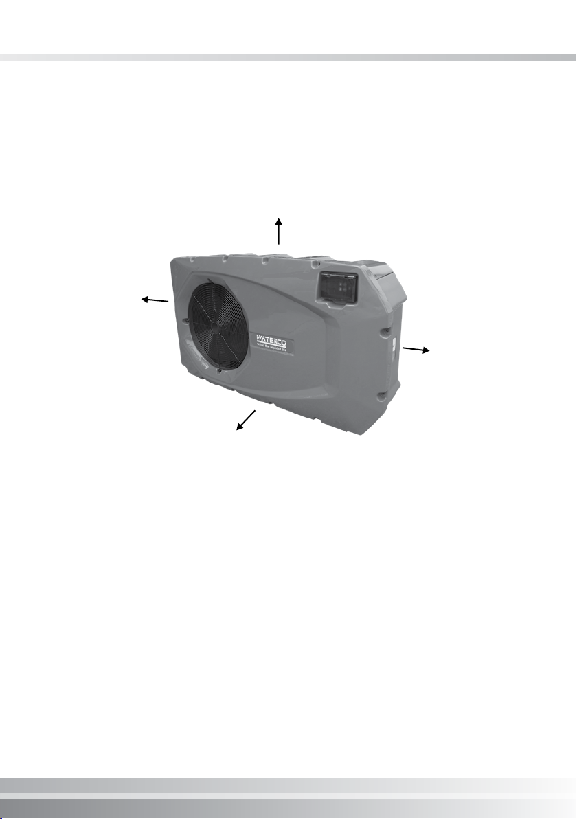
Air is pulled through the evaporator coil and discharged from the top grill. Clearances
must be allowed in front and around the unit for unrestricted air discharge and
service access. See Figure 1. Failure to comply to the set clearances may cause
diminished unit performance and reduced unit longevity.
Clearance to rear minimum 30cm
Clearance to side
minimum 60cm
Clearance to side
minimum 60cm
No obstruction to front
2.5m minimum

Water Piping
The supplied plumbing layout must be followed without exception:
1. pool pump
2. filter
3. pool heat pump
4.chlorinator (when installed).
Rigid PVC piping is recommended with all joints primed and glued with a suitable PVC
adhesive cement. If rigid PVC pipe is not available,a suitable flexible hose of adequate
diameter may be utilised with stainless steel clamps. When the piping installation is
complete, operate the pool pump and check the system for leaks. Then check the
filter pressure gauge to see that excessive pump head pressure is not indicated.
Water Flow Rate
The recommended water flow rate range varies depending on the size of the heat
pump to ensure maximum heat transfer efficiency is within the specified limits. The
optimal flow rate is the mid point of this range. Use the bypass valve to adjust the
flow rate to within the recommended range. See Performance Specifications table
page 13.
Water By-pass Kit
A bypass kit consisting of 3 X two way valves must be installed for adjustment of
water flow and ease of service. Waterco offer prefabricated water bypass kits to fit
their heat pump domestic range. Ask your local Waterco sales office for details.
07 I Pool Heat Pump

Pool Heat Pump I 08
1. A check valve or a loop MUST be installed between the pool heat pump and any
automatic chlorinator to prevent highly chlorine concentrated water from flowing
back to the pool heat pump when the pool pump is not running.
2. These units are fitted with a flow switch which are not effected by water pressure.
Therefore, the fitment of a flow check valve due to the installed height either
above or below water level is not required.
3. For units installed above the pool water level the return water to the pool valve on
the bypass valve set should be closed approximately 15-20% to ensure the heat
exchanger is completely full of water to allow the heat transfer to occur.
Plumbing Diagram
Plumbing connections to
the heater must be made
by hand only as it may
break the water Inlet or
Outlet connections.
HEAT PUMP
PUMP
Filter
SPA POOL
SPA POOL
Water Out
Water By-pass
Water In
From Spa From Pool
3 Way Valve
To Spa
Vertical Trap
Check
Valve
Chlorinator
or Chlorine
Generator
To Pool
MultiCyclone
!
09 I Pool Heat Pump
Electrical
All electrical work should be performed by a fully qualified and licensed electrician
in accordance with local electrical codes.
An adequate circuit breaker and copper wiring must be used. Electrical requirements
are available on the name plate of the pool heat pump. It may be necessary to install
an earth leakage circuit breaker.
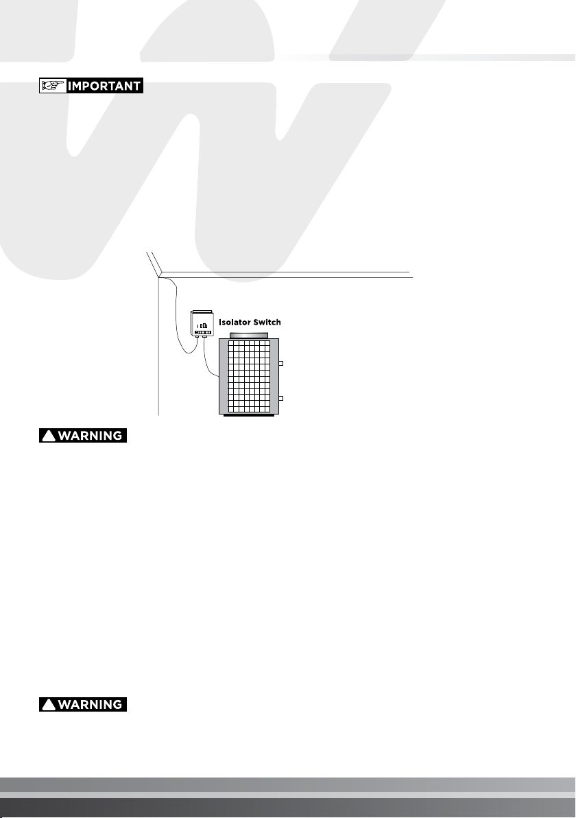
Waterco recommend connecting the unit to an isolating switch to allow ease of
service and maintenance.
Electrical Connection
Standard 60 Hz power supply : 208/240 v - 60Hz-1 phase
Standard 50 Hz power supply : 208/240 v - 50Hz-1 phase
Breaker Size
Please consult name plate on the base or the side of your pool heat pump for starting
amperage and required breaker size.
Electrical Wire Size
Please consult a qualified and licensed electrician.
THE POOL HEAT PUMP MUST BE DISCONNECTED BEFORE
OPENING THE ACCESS PANEL.
!
The power cable ground must be connected to the electrical
panel and to the ground lug of the pool heat pump. An
improper installation may be a potential cause of fire,
electrical shock or injury.
!
This manual suits for next models
3
Table of contents
Popular Heat Pump manuals by other brands


Mitsubishi Electric
Mitsubishi Electric PUZ-SWM60VAA Service manual

Dimplex
Dimplex LI 16I-TUR Installation and operating instruction

Carrier
Carrier WSHP Open v3 Integration guide

TGM
TGM CTV14CN018A Technical manual

Carrier
Carrier 38MGQ Series installation instructions

Kokido
Kokido K2O K880BX/EU Owner's manual & installation guide

Viessmann
Viessmann VITOCAL 300-G PRO Type BW 2150 Installation and service instructions

Carrier
Carrier 48EZN installation instructions

Viessmann
Viessmann KWT Vitocal 350-G Pro Series Installation and service instructions for contractors

Ariston
Ariston NIMBUS user manual

Weishaupt
Weishaupt WWP L 7 Installation and operating instruction

GE
GE Zoneline AZ85H09EAC datasheet