ELAN DIGITAL SYSTEMS HD717 User manual

Elan Digital Systems Ltd. 1 HD717 USER’S
GUIDE
ELAN DIGITAL SYSTEMS LTD.
LITTLE PARK FARM ROAD,
SEGENSWORTH WEST,
FAREHAM,
HANTS. PO15 5SJ.
TEL: (44) (0)1489 579799
FAX: (44) (0)1489 577516
e-mail: support@elan-digital-systems.co.uk
website: www.pccard.co.uk
HD717 PC-CARD USER’S GUIDE
ALSO COVERS HD712,HD713
REVISION HISTORY
ISSUE PAGES DATE NOTES
1 59 11.04.97 FIRST ISSUE
2 60 28.04.97 NEW FEATURES
3 60 09.09.97 SCC DATA/CLK TIMING NOTE p15
4 58 28.01.98 SIMPLIFY PCCARDGO TEXT
5 58 25.03.98 RS422 ENABLE BIT (GSR2)
6 52 24.07.98 REMOVED SOFTWARE SECTION
TO PCCARDGO.DOC
7 52 10.08.98 HD712 ADDED
8 52 16.04.99 HD713 ADDED
9 52 29.01.01 LOOPBACK CONNECTIONS
10 52 11.04.02 LOOPBACK CONNECTIONS
11 55 23.04.02 Figure 3.1.3-1 Added

Elan Digital Systems Ltd. 2 HD717 USER’S
GUIDE
CONTENTS
1. OVERVIEW..................................................................................................5
2. ABOUT THE HD717 ....................................................................................6
2.1 THE SERIAL COMMS CONTROLLER........................................................6
2.2 LOW RATE DATA INTERFACES.................................................................7
2.3 DIGITAL I/O INTERFACE..............................................................................9
3. CONTROLLING THE HD717.....................................................................10
3.1 SCC....................................................................................................................10
3.1.1 SCC I/O PORTS...........................................................................................10
3.1.2 SCC BASIC CONFIGURATION................................................................11
3.1.3 SCC TX/RX CLOCK SELECTION............................................................14
3.1.4 SCC TRANSMIT PROCEDURE................................................................17
3.1.5 SCC RECEIVE PROCEDURE....................................................................21
3.1.6 RS485 SUPPORT (Issue 2(+) HD717 & HD712,713 Cards Only).............23
3.2 LOW RATE DATA..........................................................................................24
3.2.1 TRANSMIT..................................................................................................24
3.2.2 RECEIVE.....................................................................................................28
3.3 HANDLING INTERRUPTS............................................................................31
3.4 USING THE DIGITAL I/O PINS...................................................................35
4. HD717 REGISTER INTERFACE ...............................................................36
4.1 SCC CONTROL (IOBASE+0).........................................................38
4.2 SCC DATA (IOBASE+1).....................................................................38
4.3 IPR READ / IMR WRITE (IOBASE+2).....................................39
4.4 LRD RX LO READ / TX LO WRITE (IOBASE+3)..............40
4.5 LRD RX HI READ / TX HI WRITE (IOBASE+4)................40
4.6 SUB REG DATA (IOBASE+5).........................................................41
4.7 SUB REG IDX WRITE ONLY (IOBASE+6)............................41
4.8 RX 4K FIFO READ / TX 4K FIFO WRITE (IOBASE+7).43

Elan Digital Systems Ltd. 3 HD717 USER’S
GUIDE
4.9 PCR (SUB REG 0)..................................................................................44
4.10 LBG (SUB REG 1)................................................................................45
4.11 SCS (SUB REG 2).................................................................................46
4.12 DIDI READ / DIDO WRITE (SUB REG 3)............................47
4.13 DIR (SUB REG 4).................................................................................47
4.14 SCR (SUB REG 5)................................................................................48
4.15 MSR READ ONLY (SUB REG 6)................................................49
4.15 IMR READ ONLY (SUB REG 7).................................................50
5. HARDWARE SPECIFICATION..................................................................51
5.1 PINOUT.............................................................................................................51
5.2 POWER CONSUMPTION..............................................................................53
5.3 MECHANICAL................................................................................................53
5.4 ENVIRONMENTAL........................................................................................53
5.5 LOOP BACK CONNECTIONS FOR TEST SOFTWARE.........................53
6. SOFTWARE...............................................................................................54
6.1 UNIVERSAL DRIVER....................................................................................54
6.2 C SOURCE CODE...........................................................................................54
7. OPERATIONAL PRECAUTIONS .............................................................55

Elan Digital Systems Ltd. 4 HD717 USER’S
GUIDE
Disclaimer
This document has been carefully prepared and checked. No responsibility can be
assumed for inaccuracies. Elan reserves the right to make changes without prior notice
to any products herein to improve functionality, reliability or other design aspects.
Elan does not assume any liability out of the use of any product described herein;
neither does it convey any licence under its patent rights not the rights of others. Elan
products are not authorised for use as components in life support services or systems.
Elan should be informed of any such intended use to determine suitability of the
products.
Source code supplied with Elan PC-Cards is provided “as-is” with no warranty, express
or implied, as to its quality or fitness for a particular purpose. Elan assume no liability
for any direct or indirect losses arising from use of the supplied code.
Copyright © 1996,1997 Elan Digital Systems Ltd.

Elan Digital Systems Ltd. 5 HD717 USER’S
GUIDE
1. OVERVIEW
Before using the HD717, take some time to read the section
“OPERATIONAL PRECAUTIONS”.
The HD717 card is a general purpose Serial Comms PC-Card with
the following features:
•Z85233 Serial Comms Control device (SCC) capable of both
synchronous and asynchronous protocols. SDLC mode can
operate at up to 4MBits / sec (also known as HDLC mode)
• 16MHz base clock rate to SCC (12MHz:HD712, 13MHz:HD713)
•Flexible clock routing network for synchronous modes, including
card generated 4,2,1 or 0.5MBits/sec clock to SCC’s TX and RX
clock pins (12,3,1.5,0.75MBits/s on HD712 or 16,4,2,1,0.5MBits/s on Iss2.01+
HD717, 13,3.25,1.625,0.8125MBits/s on HD713).
•RS422 interface drivers and receivers for SCC
•Issue 2+ HD717 and all HD712,713 cards have support for
RS485 shared data bus scheme
•4Kx8 transmit and receive FIFOs to decouple PC from high
speed transfers
•Bipolar RZ input and output to ARINC 717 spec with bit rates
from 768 to 6144 bits/sec
•Harvard Biphase (or “FM1”) input and output to ARINC 717
spec with bit rates from 768 to 6144 bits/per sec
•8 digital I/O lines with programmable 47K pull up-down.
This guide aims to familiarise you with the way that the HD717
works and so will help you to maximise its performance in your
application.
Elan will be happy to quote for either customisation of the HD717 if
its exact specifications do not quite meet your needs, or to create
complete application software.

Elan Digital Systems Ltd. 6 HD717 USER’S
GUIDE
2. ABOUT THE HD717
2.1 THE SERIAL COMMS CONTROLLER
The HD717 uses the “industry standard” 85233 Serial Comms
Controller chip (or SCC). This device contains all the logic required
to handle a variety of synchronous and asynchronous serial
protocols. Its operation is not detailed in this document due to its
complexity and the possibility of data book transcription errors.
Instead the reader is strongly advised to obtain the latest User’s
Guide for the generic family of controllers from Zilog Inc. The full
title of the guide is:
“SCC USER’S MANUAL, Zilog Inc, Part No. DC-8293-02”
This is referred to as [REF 1] in this document.
In the UK, Zilog can be reached at (44) (0)1628 39200.
The HD717 maps the SCC directly into the PC’s IO space and so the
device appears just as it would if it were on say an ISA card or PCI
card. The only fundamental difference in the way the SCC operates
on the HD717 is that the data for TX and RX is buffered by 4096 x 8
FIFOs. On an ISA card, it is common to use the SCC in DMA
mode, where two DMA channels are used (one for TX and one for
RX data paths). This is precluded in PCMCIA as only one physical
DMA channel is possible. To overcome this, the HD717 uses
control logic in the card to act like a DMA controller to the SCC.
This means that the SCC must be set to operate in DMA mode even
though the source and destination for the DMA requests never leave
the PC card itself. Instead the data transfers operate transparently (to
the PC) into and out-of the FIFOs. The PC is notified by interrupt
when either the TX FIFO falls below half full or the RX FIFO rises
above half full or the SCC signals a “special condition” e.g. End Of
Message in synchronous modes.
The 4K FIFO buffers effectively shadow normal SCC operations: it
is still possible for the PC to directly read and write the SCC’s own
internal data buffers although doing so must be considered carefully
as accessing the SCC data registers directly may cause missed DMA

Elan Digital Systems Ltd. 7 HD717 USER’S
GUIDE
cycles to the 4K FIFOs (the read or write acts as the DMA
acknowledge).
The following block diagram may help to clarify the role of the 4K
FIFOs in the system:
OSC:
16MHz HD717
12MHz HD712
TRxC PIN
OSC÷4,8,16,32MHz
TXClkExt
TX CLK IN
RX DATA
TX DATA
TX CLK OUT
RXClkExt
RTxC PIN
RX CLK IN
RX CLK OUT
SCC
4K
FIFO
RX
4K
FIFO
TX
LOGIC
PIO
PIO
DMA
DMA
PC
RS422
PCLK PIN
Rterm=220ohms
TRxCEn
HD712/Iss2.01+HD717
OSC÷4,8,16,32MHz
Figure 2.1-1 Functional Block Diagram of SCC + FIFOs
2.2 LOW RATE DATA INTERFACES
The HD717 provides inputs and outputs for two of the common
ARINC 717 serial data protocols, namely Bipolar Return-to-Zero
and Harvard Biphase (or FM1). The input and output circuits
function independently except that i) the encoding mode applies to
both input and output at the same time (i.e. can’t send BRZ and
receive Biphase simultaneously). ii) the input and output data rates
are derived from the same clock so that the send and receive circuits
always run at the same bit rate.
Data rates are software programmable and cover the “commonly”
used bit/sec settings of 768,1536,2304,3072,6144.

Elan Digital Systems Ltd. 8 HD717 USER’S
GUIDE
The waveshapes for the two protocols are summarised below. Refer
to the ARINC specification for a more complete definition.
BIPOLAR R-Z
LINE A to LINE B +10V
-10V
0V
1 10 0 0
+5V
-5V
0V
+5V
-5V
0V
LINE A to GND
LINE B to GND
BIT-CELL
HARVARD BIPHASE
LINE A to LINE B +5V
-5V
0V
1 10 0 0
+5V
-5V
0V
+5V
-5V
0V
LINE A to GND
LINE B to GND
BIT-CELL
As can be seen, there is sufficient clocking information in both
waveforms to allow complete asynchronous reception without the
source clock present. The BRZ code is inherently simple to decode
due to its “transition-per-bit” nature. Harvard Biphase is more
complex to decode and relies on there being at least one zero in the
data stream to ensure the receiver is correctly in sync with the
transmitter. The HD717 provides a status bit and various control

Elan Digital Systems Ltd. 9 HD717 USER’S
GUIDE
signals to control how it will behave when it first receives Biphase
data.
Note that the transmitter circuits in the HD717 are also capable of
operating in NRZ and FM0 modes. The receiver can cope with FM0
input data but cannot receive NRZ data (NRZ is simply generated as
“A-B”=5V ⇒Logic ‘1’, “A-B”= -5V ⇒Logic ‘0’).
The output drivers used for the Low Rate Data are slew rate limited
as required by ARINC specifications (typical 10-20us 10-90%).
Additionally, they are series terminated (in both A and B circuits)
with 22ohm resistors. This aids in driving highly capacitative loads
(i.e. very long cables).
2.3 DIGITAL I/O INTERFACE
8 Digital I/O drivers are provided on the HD717 to use as general
purpose control outputs and/or status monitoring inputs. The I/O
pins are logically grouped together in clusters of 1,1,2,4 I/O pins
(i.e. total = 8). These groupings define how the pins are set to inputs
or outputs. The groupings allow for any number of inputs or outputs
by using the correct combination of clusters. Additionally, each I/O
pin is “pulled” via a 47K resistor to a global control signal called
“DIOPull”. This signal can be set low or high in software to affect a
pull up or a pull down. The default (power-on) state is down.
The I/O pins are clamped to the internal Vcc and ground rails using
fast schottky diodes. This affords a good level of protection against
static damage.

Elan Digital Systems Ltd. 10 HD717 USER’S
GUIDE
3. CONTROLLING THE HD717
3.1 SCC
3.1.1 SCC I/O PORTS
The control registers of the SCC are mapped for read and write at
IOBASE+0. The data registers (i.e. TX and RX data buffers) are
mapped at IOBASE+1. It is not recommended to directly access the
SCC data registers unless you intend to run the serial data at very
low rates. It is far easier to allow the SCC to DMA its data to/from
the 4K FIFOs and configure the SCC to create interrupts to notify
the PC to collect or deposit data to the FIFOs as required.
The SCC control registers use a two access process. The first access
to IOBASE+0 is a write, which contains the “pointer” to the SCC
internal register to read or modify. The second access will be a read
or write to IOBASE+0 to read or write to the register pointed to by
the first access. The two access sequence must be maintained by
software to ensure that incorrect accesses to internal registers are not
made. The only exception is when the first write cycle is to execute
one of the “commands” that are controlled by WR0 (Write Register
0 in Zilog terms). Here, no second cycle is required as the data is
essentially implicit in the command. Refer to [REF 1] for details.
Table of contents
Other ELAN DIGITAL SYSTEMS Computer Hardware manuals
Popular Computer Hardware manuals by other brands

EMC2
EMC2 VNX Series Hardware Information Guide

Panasonic
Panasonic DV0PM20105 Operation manual

Mitsubishi Electric
Mitsubishi Electric Q81BD-J61BT11 user manual

Gigabyte
Gigabyte B660M DS3H AX DDR4 user manual

Raidon
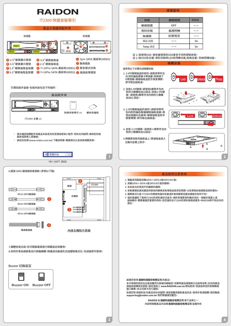
Raidon iT2300 Quick installation guide

National Instruments
National Instruments PXI-8186 user manual