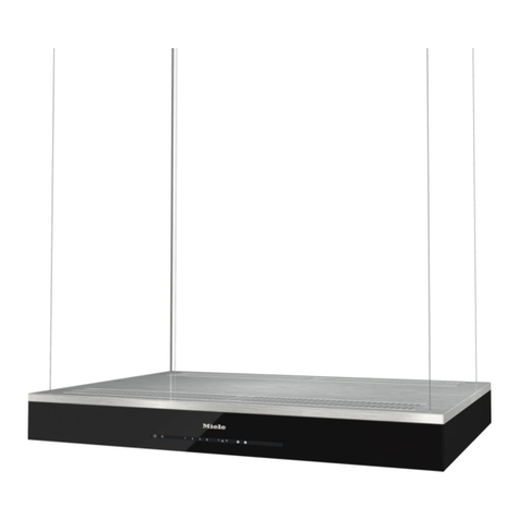
EF CK-SPECCHIO User manual

DESIGNER HOOD MODEL: CK-SPECCHIO
THE BEAUTY OF SIMPLICITY
USER MANUAL

2
Fig.1
Fig.2 Fig.3
Fig.4 Fig.5

3
A B
Fig.6 Fig.7
Fig.8 Fig.9
Fig.10 Fig.11
Fig.12 Fig.13
Fig.14

4
Fig.15 Fig.16
Fig.17 Fig.18
Fig.17 Fig.18Fig.17 Fig.18
Fig.17 Fig.18
GENERAL
Carefully read the following important information regarding installation
safety and maintenance. Keep this information booklet accessible for further
consultations. The appliance has been designed for use in the ducting
version (air exhaust to the outside – Fig.1B), filtering version (air circulation
on the inside – Fig.1A) or with external motor (Fig.1C).
SAFETY PRECAUTION
1. Please take note that when the cooker hood is operating simultaneously
with an open fireplace or burner that depend on the air in the environment,
the cooker hood may removes the air from the environment which a burner
or fireplace need for combustion. The negative pressure in the environment
must not exceed 4Pa (4x10⁻⁵ bar). Provide adequate ventilation in the
environment for a safe operation of the cooker hood. Follow the local laws
applicable for external air evacuation.

5
Before connecting the model to the electricity network:
- control the data plate (positioned inside the appliance) to ascertain that the
voltage and power correspond to the network and the socket is suitable. If in
doubt please ask qualified electrician for help.
2. WARNING!
In certain circumstances electrical appliances may be a danger hazard.
A) Do not check the status of the filters while the cooker hood is operating
B) Do not touch bulbs or adjacent areas, after prolonged use of the lighting
installation.
C) Flambe cooking is prohibited underneath the cooker hood
D) Avoid free flame, as it is damaging the filters and can cause fire hazard
E) Constantly check food frying, the overheated oil may become a fire
hazard
F) Disconnect the electrical plug prior to any maintenance.
G) There shall be adequate ventilation in the room when the range hood is
operating
H) There is a risk of fire if cleaning is not carried out in accordance with the
instructions
I) If the supply cord is damaged, it must be replaced by the manufacturer or
its service agent or a similarly qualified person
J) This appliance is not intended for use by persons (including children) with
reduced physical, sensory or mental capabilities, or lack of experience
and knowledge, unless they have been given supervision or instruction
concerning use of the appliance by a person responsible for their safety.
K) Children should be supervised to ensure that they do not play with the
appliance.
L) The air must not be discharged into a flue that is used for exhausting
fumes from appliances burning gas or other fuels
M) The minimum distance between the supporting surface for the cooking
vessels on the hob and the lowest part of the range hood shall be at least
65cm. The instructions for installation of the gas hob specify a greater
distance has to be taken into account if requirement stated
O) Regulation concerning the discharge of air has to be fulfilled.
INSTALLATION INSTRUCTIONS
Assembly and electrical connections must be carried out by specialized

6
personnel.
• Electric Connection
The appliance has been manufactured as class I, therefore earth cable is
necessary.
The connection to the mains is carried out as follows:
If the plug is not provided, connect the electrical load as indicated on the
description label. When a plug is provided, the cooker hood must be
installed in order that the plug is easy to access.
An omnipolar switch with a minimum aperture of 3mm between contacts; in
line with the electrical load and local standards, must be placed between the
appliance and the network in the case of direct connection to the electrical
network.
• The minimum distance between the support surfaces of the cooking pots on
the cooker top and the lowest part of the cooker hood must be at least 65 cm.
If a connection tube composed of two parts is used, the upper part must be
placed outside the lower part.
Do not connect the cooker hood exhaust to the same conductor used to
circulate hot air or for evacuating fumes from other appliances generated by
other than an electrical source.
Before proceeding with the assembly operations, remove the anti-grease
filter(s) (Fig.5) so that the unit is easier to handle.
In the case of assembly the appliance, in the suction version prepare the hole
for evacuation of the air.
• FIXING TO THE WALL
Drill the holes A respecting to the distances indicated (Fig.2).
Fix the appliance to the wall and align it in horizontal position to the wall
units. When the appliance has been adjusted, fix the hood using the screws
A.
For the various installations use screws and screw anchors suited to the type
IEC227 North America
L=live Brown Black
N=neutral Blue White
E=earth Green/Yellow
Green

7
of wall (e.g. reinforced concrete, plasterboard, etc.). If the screws and screw
anchors are provided with the product, kindly check the screws are suitable
for the type of wall in which the hood is to be fixed.
• FIXING THE DECORATIVE TELESCOPIC FLUE
Arrange the electrical power supply within the dimensions of the decorative
flue. If your appliance is to be installed in the ducting version or in the
version with external motor, prepare the air exhaust opening. Adjust the
width of the support bracket of the upper flue (Fig.3). Then fix it to the
ceiling using the screws A (Fig.2) make sure that it is in line with your hood
and respecting the distance from the ceiling indicated in Fig.2. Connect the
flange C to the air exhaust hole using a connection pipe (Fig.4).
To transform the hood from a ducting version into a filtering version, ask
your dealer for the charcoal filters and please follow the installation
instructions.
• FILTERING VERSION
Install the hood and the two flues as described in the paragraph for
installation of the hood in ducting version. To assemble the filtering flue
refers to the instructions contained in the kit. If the kit is not provided, please
order it from your dealer. The charcoal filters must be fitted in the ducting
unit located inside the hood.
USE AND MAINTENANCE
• It is recommended to operate the appliance prior to cooking.
It is recommended to leave the appliance in operation for
15 minutes after cooking is terminated in order to completely eliminate
cooking vapors and odours.
The proper function of the cooker hood is conditioned by the regularity of
the maintenance operations, in particular, the active carbon filter.
• The anti-grease filters capture the grease particles suspended in the air, and
are therefore subject to clogging according to the frequency of the use of the
appliance.
In order to prevent fire hazard, it is recommendable to clean the filter at a
maximum of 2 months by carrying out the following instructions:
- Remove the filters from the cooker hood and wash them in a solution of

8
water and neutral liquid detergent, leaving to soak.
- Rinse thoroughly with warm water and leave to dry.
- The filters may also be washed in the dishwasher.
Please take note that the aluminum panels may alter in color after several
washes.
• The active carbon filters purify the air that is replaced in the environment.
The filters are not washable or reuseable and must be replaced at maximum
every four months. The saturation of the active carbon filter depends on the
frequency of use of the appliance, also by the type of cooking and the
regularity of cleaning on the anti-grease filters. (Fig 6) To remove the
charcoal filters place our hand on one filter at a time and turn it toward the
front part. The charcoal filter can now be removed. Always ensure to replace
both filters at the same time.
• Clean the fan and other surfaces of the cooker hood regularly using a cloth
moistened with denatured alcohol or non abrasive liquid detergent.
• The illumination installation is designed for use during cooking and not for
prolonged general illumination of the environment. Prolonged use of the
illumination installation notably reduces the duration of the bulb.
Use a one-edged screwdriver or any other appropriate tool to lift and remove
the overhead light fixture. Replace the damaged lamp. Use only halogen
lamps as the original specification, avoiding contact with hands. Return the
light fixture to its position (snap fastening). (Fig. 7)
• How to replace the charcoal filters:
(1)Push the right middle corner on the glass of the decoration door (Fig.A),
the decoration door will open (Fig.B).
(2)Take out the aluminum filter (Fig.C);
(3)Push the clips on the charcoal filters and then pull back, then the charcoal
filters can be taken down (Fig.D).
Fig.A Fig.B

9
Fig.C Fig.D
• How to replace the charcoal filters
for 35 series
1. Push the middle bottom edge of the glass door (Fig.E)
2. The inside gas spring will help you to open the glass door , and fixed at
an angle (Fig.F)
3. Take out the aluminum filter (Fig.G)
4. Push the buckle of the charcoal filters with both hands then pull out.
The charcoal filters can be taken down. (Fig.H)
Fig.E Fig.F
Fig.G Fig.H

10
• FUNCTION KEYS: (Fig.8)
A = OFF
B = SPEED I / OFF
C = SPEED II / OFF
D = SPEED III / OFF
E = LIGHT
• If your appliance does not have the INTENSIVE speed function, press key
A for two seconds and it will be activated for 15 minutes after which it will
return to the previously set speed. If the function program of the unit is
active the LED will flash.
By pressing any key except the key for the light, the hood will return
immediately to its normal functioning.
The “automatic stop timer” mode delays stopping operation of the hood,
the mode will continue functioning for 15 minutes at the operating speed
set at the time this function is activated.
FUNCTION KEYS: (Fig.10)
A == OFF
B == SPEED 1/“-”Control
C == SPEED 2/“+”Control
D == SPEED 4
E == LIGHT
By pressing key B、C or D individually, the speed for each key will be the
same as above table. At the same time indicated light will flash on the each
function key button. To stop the speed function press key A.
If Speed 3 is required,press key C adjust“+”. At Speed 3 program both key
B and key C indication light will flash on each function key button.
To on the light press key E. To off the light press key E again.
FUNCTION KEYS: (Fig.11)
A == Automatic Stop Timer —15 minutes
B == Speed 1/“-”Control
C == Speed 2/“+”Control
D == Speed 4
E == Light
By pressing key B、C or D individually, the speed for each key will be the
same as above table. At the same time indicated light will flash on the each
function key buttons. To stop the speed function press key A.
•
FUNCTION KEYS
:
(Fig.9)
A= TIMER – 15 MINUTES
B= SPEED I
C= SPEED II
D= SPEED III
E =LIGHT
Table of contents
Other EF Ventilation Hood manuals

EF
EF CK-Vetro User manual

EF
EF EFCH 9401 HM SS User manual

EF
EF EFCH 9232 HM SS User manual

EF
EF POWER SLIM 90X/V User manual

EF
EF EFCH 9201T SS User manual

EF
EF CK-LUME User manual

EF
EF EFCH 9111 910 HM SS User manual

EF
EF EFCH 6101 HM SS User manual

EF
EF EFCH9103 HM SS User manual

EF
EF EFCH 9211 HM SS User manual