Edco VAC-100 User manual

Operator’s Instruction Manual
and Parts List
VAC-100
VAC-100-I-0315
E-SPTS-I-0809
EQUIPMENT DEVELOPMENT CO., INC.
100 Thomas Johnson Drive, Frederick, MD 21702-4600 USA
Phone: 301-638-3326 • 301-663-1600
Fax: 800-447-3326 • 301-663-1607
edcoinc.com • [email protected]

Page 2
VAC-100-I-0315
800-638-3326 • edcoinc.com • [email protected]
EQUIPMENT DEVELOPMENT CO., INC.
READ AND UNDERSTAND THE OPERATORS INSTRUCTION MANUAL THOROUGHLY
BEFORE ATTEMPTING TO OPERATE THIS EQUIPMENT.
Death or serious injury could occur if this machine is used improperly.
Extreme care must be taken when operating electric
models with water present: Ensure power cord is prop-
erly grounded, is attached to a Ground-Fault-Interrupter
(GFI) outlet, and is undamaged.
• Check all electrical cables - be sure connections are tight and
cable is continuous and in good condition. Be sure cable is
correctly rated for both the operating current and voltage of
this equipment.
• Improper connection of the equipment-grounding conductor can
cian or service person if there is any doubt as to whether the
outlet is properly grounded. Adhere to all local codes and
ordinances.
• NOTE: In the event of a malfunction or breakdown, grounding
provides a path of least resistance for the electric current to
dissipate. The machine is equipped with a grounded plug
and must be connected to an outlet that is properly installed
and properly grounded. DO NOT modify the plug provided on
electrician install the proper receptacle.
• Switch motor OFF before disconnecting power.
• Engine exhaust from this product contains
chemicals known to the State of California to
cause cancer, birth defects or other reproductive
harm.
•
should only be dispensed in well ventilated areas,
and with a cool engine.
• Small gasoline engines produce high concentrations of car-
bon monoxide (CO) example: a 5 HP 4 cycle engine opera-
tion in an enclosed 100,000 cu. ft. area with only one change
of air per hour is capable of providing deadly concentrations
same area will produce noxious fumes in less than 30 min-
utes. Gasoline or propane powered equipment should not be
used in enclosed or partially enclosed areas. Symptoms of
CO poisoning include, headache, nausea, weakness, dizzi-
ness, visual problems and loss of consciousness. If symp-
toms occur - get into fresh air and seek medical attention
immediately.
SAFETY
MESSAGES
SAFETY MESSAGES
Indicates an imminent hazard which, if not avoid-
ed, will result in death or serious injury.
Indicates an imminent hazard which, if not avoid-
ed, can result in death or serious injury.
Indicates hazards which, if not avoided, could
result in serious injury and or damage to the
equipment.
• Safety Instructions are proceeded by a graphic alert symbol
of DANGER, WARNING, or CAUTION.
ELECTRICAL POWERED EQUIPMENT
GASOLINE/PROPANE POWERED EQUIPMENT
• Equipment should only be operated by trained personnel in
good physical condition and mental health (not fatigued). The
operator and maintenance personnel must be physically able
to handle the bulk weight and power of this equipment.
• This is a one person tool. Maintain a safe operating distance
to other personnel. It is the operators’ responsibility to keep
other people (workers, pedestrians, bystanders, etc.) away
during operation. Block off the work area in all directions with
roping, safety netting, etc. for a safe distance. Failure to do so
them to harmful dust and noise.
• This equipment is intended for commercial use only.
• For the operator’s safety and the safety of others, always keep
all guards in place during operation.
• Never let equipment run unattended.
• Personal Protection Equipment and proper safety attire must
be worn when operating this machinery. The operator must
wear approved safety equipment appropriate for the job such
as hard hat and safety shoes when conditions require. Hear-
ing protection MUST be used (operational noise levels of this
equipment may exceed 85db). Eye protection MUST be worn
at all times.
Keep body parts and loose clothing away from moving
parts. Failure to do so could result in dismemberment
or death.
• Do not modify the machine.
• Stop motor/engine when adjusting or servicing this equipment.
materials. Sparks from the cutting-action of this machine
GENERAL INSTRUCTIONS
DUST WARNING
Some dust created by power sanding, sawing,
grinding, drilling, and other construction activi-
ties contains chemicals known to cause cancer,
birth defects, or other reproductive harm. Some
examples of these chemicals are:
• Lead from lead-based paints, and
• Crystalline silica from bricks and concrete and other
masonry products.
Your risk of exposure to these chemicals varies depending
on how often you do this type of work. To reduce your risk:
work in a well ventilated area, use a dust control system, such
as an industrial-style vacuum, and wear approved personal
safety equipment, such as a dust/particle respirator designed
• Do not disconnect power by pulling cord. To disconnect, grasp
the plug, not the cord.
• Unplug power cord at the machine when not in use and before
servicing.

Page 3
VAC-100-I-0315
E-SPTS-I-0809
800-638-3326 • edcoinc.com • [email protected]
EQUIPMENT DEVELOPMENT CO., INC.
Operator’s Instruction Manual
VAC-100
Table of Contents
HOW TO ORDER REPAIR PARTS
To insure product safety and reliability, always use genu-
ine EDCO replacement parts when making repairs to the
equipment.
When ordering parts, please specify the MODEL and SERI-
AL NUMBER of the machine as given on the NAMEPLATE.
In addition, give part number, description and quantity as
listed on the parts list.
Please note: Due to improvements and changes in the
equipment the illustrations shown may be different from
the actual machine.
Toll Free: Voice 1-800-638-3326 • Fax 1-800-447-3326
FILL IN INFORMATION BELOW
DATE OF PURCHASE _____________________________
MODEL NO. _____________________________________
SERIAL NO. _____________________________________
SKU NO. ________________________________________
Figure 1
Safety Messages / General Instructions ..............................................................................2
How To Order Replacement Parts ......................................................................................3
Start-up Operation ...............................................................................................................4
Filter Inspection ...................................................................................................................5
Filter Removal .....................................................................................................................6
Filter Installation ..................................................................................................................7
Motor Cover Disassembly ...................................................................................................8
AMETEK Motor Brush Inspection ........................................................................................9
ELECTRO Motor Brush Inspection....................................................................................10
Filter Installation ................................................................................................................ 11
Illustration 1 : 1000 Motor Deck Assembly ...................................................................12-13
Illustration 2 : 1000 Switch Assembly ...........................................................................14-15
Illustration 3 : Filter Assemblies ....................................................................................16-17
Illustration 4 : Base Assembly.......................................................................................18-19
Illustration 5 : Dust Pan Lever Assembly ......................................................................20-21
Illustration 6 : Inlet Assemblies .....................................................................................22-23
Illustration 7 : Hose & Adaptor ...........................................................................................24
SMI Dust Silica Warning ....................................................................................................25
Notes Page ........................................................................................................................26
Limited Equipment Warranty .............................................................................................27
NOTE: Due to improvements your machine may not appear the same as the pictures in this manual.

Page 4
VAC-100-I-0315
800-638-3326 • edcoinc.com • [email protected]
EQUIPMENT DEVELOPMENT CO., INC.
GETTING STARTED WITH YOUR NEW VAC 100
VORTEX 100 STANDARD INSTRUCTIONS:
START-UP OPERATION
NOTE: 1. This machine is to be operated for Dry use only. Using this machine in an wet environment will damage the machine, 2.
motor, 3. Be sure to check the dust pan during operation. When pan is 3/4 full, it should be emptied out.
Pull up on the dust pan lever to
release the dustpan. Check that
the dustpan is completely empty
then replace.
Connect the machine to the proper
power source, as indicated on the
machine’s serial tag.
Start the machine by pushing
the power switch to the ON / (I)
position.
Turn the machine off by pushing
the power switch to the OFF / (O)
open position
Before and after every use, the
the shaker bar in and out rapidly
for 10 seconds.
You should empty the dustpan
after every use as well.
CAUTION: The electrical service at the installation site must supply the voltage stamped on the machine’s serial tag. Most motors have multiple
machine. See the EDCO serial tag for proper machine voltage.

Page 5
VAC-100-I-0315
E-SPTS-I-0809
800-638-3326 • edcoinc.com • [email protected]
EQUIPMENT DEVELOPMENT CO., INC.
GETTING STARTED WITH YOUR NEW VAC 100
VORTEX 100 STANDARD INSTRUCTIONS:
FILTER INSPECTION
WARNING:
With machine off, knock material
by moving it in and out rapidly for
10 seconds.
Pull up on dustpan lever to release
Turn vacuum motor on. This will
Remove dustpan and lock the rear
casters. Carefully tip the machine
back onto the push handle.
Remove any material between the
pleats, by hand only. Inspect the
material blockage; Inlet for wear.
Vacuum off any excess material
with another vacuum, making sure
not to use any sharp tools that
tears or holes. (see page 6 for
instructions)
Carefully tip the machine back
onto the casters, and replace the
dustpan. Lock into position with
the foot-actuated lever.

Page 6
VAC-100-I-0315
800-638-3326 • edcoinc.com • [email protected]
EQUIPMENT DEVELOPMENT CO., INC.
GETTING STARTED WITH YOUR NEW VAC 100
VORTEX 100 STANDARD INSTRUCTIONS:
FILTER REMOVAL
WARNING:
Place the vacuum under pressure
rigid material, and turning on the
vacuum.
Remove all of the housing
component socket truss screws
with a 5/32 hex-wrench. Turn the
vacuum off.
Separate and remove the motor
deck from the housing.
Disconnect the motor deck
ground wire from the subsequent
assembly via the push-on terminal.
Remove the handle bar bracket
screws with a 5/32 hex-wrench
until the brackets come loose.
spacer assembly ground wire from
the base via push on terminal.
spacer assembly.
insert. Inspect and replace as
needed.
NOTE:
representative if either is the case.

Page 7
VAC-100-I-0315
E-SPTS-I-0809
800-638-3326 • edcoinc.com • [email protected]
EQUIPMENT DEVELOPMENT CO., INC.
GETTING STARTED WITH YOUR NEW VAC 100
VORTEX 100 STANDARD INSTRUCTIONS:
FILTER INSTALLATION
insert, being sure to keep the black
mesh in tact between each insert.
spacer assembl making sure to
assembly ground wire from the
base via push on terminal.
Install the handle bar bracket
screws with a 5/32 hex-wrench
until the brackets are secure.
Connect the motor ground wire
from the subsequent assembly via
the push-on terminal.
Place the motor deck onto the
housing.
Place the vacuum under pressure
and rigid material, and turn on the
vacuum.
Install all of the housing
component socket truss screws
with a 5/32 hex-wrench with the
vacuum under pressure.
NOTE:

Page 8
VAC-100-I-0315
800-638-3326 • edcoinc.com • [email protected]
EQUIPMENT DEVELOPMENT CO., INC.
GETTING STARTED WITH YOUR NEW VAC 100
VORTEX 100 STANDARD INSTRUCTIONS:
MOTOR COVER DISASSEMBLY FOR ELECTRO BRUSH INSPECTION
Turn the machine off, then
disconnect the power source.
Disconnect motor terminal. Loosen the motor retaining knobs
enough to remove motor under
negative pressure.
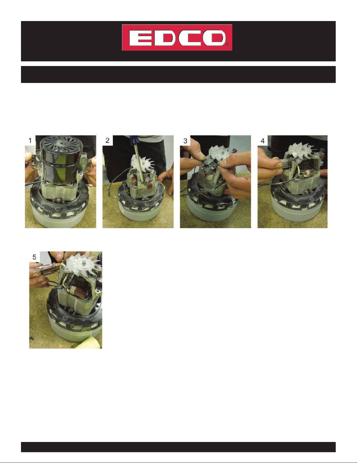
Remove the 6 screws attached to
motor assembly.
Remove the plastic motor cover
to access the top of the motor.
Remove the 2 metal motor-cap-
retaining clips located on motor
(for Amatec motors only)
NOTE:
representative if either is the case.
See page 9 for AMETEK Motor
Brush inspection instructions
See page 10 for ELECTRO Motor
Brush inspection instructions

Page 9
VAC-100-I-0315
E-SPTS-I-0809
800-638-3326 • edcoinc.com • [email protected]
EQUIPMENT DEVELOPMENT CO., INC.
GETTING STARTED WITH YOUR NEW VAC 100
VORTEX 100 STANDARD INSTRUCTIONS:
AMETEK MOTOR BRUSH INSPECTION
Remove motor fan cover by
pressing down on clips located on
each side.
Remove both sets of screws
located on one side of brush.
Repeat process for other side of
brush.
Pull brush out from wire clip.
Remove brush from wire clip by
sliding off groove. If brush is worn
down to a length of 0.25” or less,
replace brush.
To replace or reinstall brush, repeat
process in reverse.

Page 10
VAC-100-I-0315
800-638-3326 • edcoinc.com • [email protected]
EQUIPMENT DEVELOPMENT CO., INC.
GETTING STARTED WITH YOUR NEW VAC 100
VORTEX 100 STANDARD INSTRUCTIONS:
ELECTRO MOTOR BRUSH INSPECTION
NOTE: A motor brush should be replaced if its length is less than 0.25 inches.
Carefully dislodge the plastic
motor cap via the built-in hooks
on both sides of motor brush. (Tip:
followed by the other.)
brush tab upward.
Once tab is up, use pliers to pull
brush out. If brush is worn down to
a length of 0.25” or less, replace
brush.
To replace brush or reinstall brush,
hold down internal spring using the
tool supplied with brush.
While holding spring down, push
the brush back in. Remove the
brush tool once the brush is in.
Push the motor brush in until it’s
NOTE:
representative if either is the case.
Table of contents
Other Edco Vacuum Cleaner manuals

Edco
Edco VORTEX-300 Assembly instructions

Edco
Edco VAC-290 Assembly instructions

Edco
Edco GVE 370 User manual

Edco
Edco Numatic HZC 390S-2 User manual

Edco
Edco Kit AH2 User manual

Edco
Edco WV 570 User manual

Edco
Edco Numatic CVC370 User manual

Edco
Edco SLURRY PRO VACUUM Assembly instructions

Edco
Edco VAC-290 Assembly instructions

Edco
Edco Vortex 300 Datasheet