ED EPT20-15EHJ User manual

Service Manual
EPT20-15EHJ
Semi-electric Pallet Truck
MANUAL NO. SM1121 01.16

CONTENTS
Table of contents
1.LOAD WHEELS...............................................................................1
1.1 Disassembly and Assembly.......................................................1
2.DRIVE UNIT....................................................................................2
2.1 Disassembly and Assembly.......................................................2
3. TILLERHEAD .................................................................................4
4. HYDRAULIC SYSTEM...................................................................7
4.1Disassembly and Assembly........................................................7
4.2 Commissioning..........................................................................8
4.3 General Failures and Troubleshooting......................................9
4.4 Oil Seal Replacement..............................................................12
4.5 Other Issues............................................................................15
5. ELECTRICAL ...............................................................................17
5.1 Disassembly and Assembly.....................................................17
5.2 Electrical Schematic Diagram..................................................19
5.3 Power Cables..........................................................................20
5.4. Controller Troubleshooting .....................................................21
5.4.1. Fault Detection .................................................................21
5.4.2. Hand Held Programmer (Optional)...................................21
5.4.3. Fault Recording................................................................21
5.4.4. General Checkout.............................................................21
5.4.5. Diagnostic History.............................................................23
5.4.6. Test the Fault Detection Circuitry......................................23
5.4.7. Programmable Parameters ..............................................23
5.4.8. Diagnostics and Troubleshooting.....................................24
5.4.8.1. LED Diagnostics.........................................................24
5.4.9. Programmer Diagnostics...............................................24


1
REV. 03/2015
LOAD WHEELS
1.LOAD WHEELS
Place hardwood block under the Frame as shown in
Figure 01101.Remove the riser pivot shaft (index 2)
after extracting roll pin (index 1).
Remove the riser pivot shaft (index 4) after
extracting roll pin (index 3) as shown in Figure
01102.Then the wheel bracket assembly (index 5)
can be replace.
If the load wheel (index 9) is only replaced, the
riser pivot shaft (index 7) will have to be removed
after extracting roll pin (index 6) as shown in Figure
01103.Remove the bearings (index 8) and change
the load wheel (index 9).
CAUTION
In order to avoid scratching the surface of vehicle,put
a piece of rubber mat on the hardwood block.
1.1 Disassembly and Assembly

2
REV. 03/2015
DRIVE UNIT
2.DRIVE UNIT
Place hardwood blocks under the Frame as shown
in Figure 01201.Make the drive wheel hang in the air
Unfasten the four screws (index 1, Figure 01202) by
using a wrench and remove the upper cover (index 3)
and the lower cover (index 2) .
Dismantle the motor cable box (index 4) and remove
the two cables (index 5).Unscrew the three screws
(index 6) and take down the brake (index 7).Unfasten
the eight screws (index 8) and remove the gear box
cover (index 9) and the gears (index 10) .Note the
number and position for reference at assembly.Then
knock out the assembly (index 12) after unscrewing
the five screws (index 11).Refer to Figure 01203.
CAUTION
Put the hardwood block as neer the drive wheel as
possible.
2.1 Disassembly and Assembly

3
REV. 03/2015
DRIVE UNIT
Refer to Figure 01204. Knock out the motor (index
13)and pick out the oil seal (index 14).After the six
screws (index 15) have been removed, knock out
the gear ring (index 16) and the bearings (index 17)
.Then the drive wheel can be changed.
Change the brushes
If the brushes (index 7) must be repalced,the motor
will have to be dismantled.
Unfasten the three screws (index 1),Open the
moter.Remove the four screws (index 5) and pick
out the brush holder (index 6).Then the brushes
(index 7) can be replaced.Refer to Figure 01205.

4
REV. 03/2015
TILLERHEAD
3. TILLERHEAD
1. IMPORTANT-SAFETY
Verify that spring safety pin is in place. The pin
should be well rested in the holes situated on each
side of the pump housing. If the safety pin is not
rested properly in one of the holes, put pressure on
the spring using a “C” clamp pushing down on the
pump stem. Once pressure is relieved on the pin,
reinsert properly and remove clamp slowly.
2.
Insert handle pin into corresponding holes and ,
drive in one cotter pin on one side only(see arrow 2).
Note: Insert handle pin without the
handle and verify that the
center hole is facing you
(see arrow 1).
3. IMPORTANT-CHAIN
Before this step, make sure to feed the chain on the
outside of the piston stem roller (see arrow 1).If left
in its proper position, it will not be possible to insert
the handle pin and chain, breakage may occur.
Align handle holes with pump housing holes and
push through handle pin(see arrow 2).
Figure 01301
Figure 01302
12
Figure 01303
1
2
3.1 Disassembly and Assembly

5
REV. 03/2015
TILLERHEAD
4.
Make sure that handle pin is completely through
the handle and resting on the other side.
5.
Feed the chain and nut first back inside the
handle through the handle pin's center hole.
IMPORTANT-TIP
Release the up/down lever to its lowest position
to make the process easier.
Once the chain is in the proper position, check
to see that it moves freely and that it is not
obstructed.
6.
Use both hands, push on the valve cam to raise
the hook inside the housing and feed the end of
the chain in the cam.
7.
Pull down on the handle to release the tension
on the safety pin. CAREFULLY remove the
safety pin.
Figure 01304
Figure 01305
Figure 01306
Figure 01307

6
REV. 03/2015
TILLERHEAD
8.
Connect the both electrical plugs.
9. IMPORTANT-FINAL CHECK
Test all the features of the semi-electric pallet
truck before this step. The handle should be
pumped with full strokes to prime and eliminate
air in the system.
The up/down lever should be checked at the
handle’s lowest position for this puts the most
tension on the chain. Once the
pallet truck is adjusted properly and is
performing well, drive in the second cotter pin.
10.
Tie the wire harness with a tie wrap(see arrow 1)
together .
Figure 01308
Figure 01309
Figure 01310
1
7
REV. 03/2015
HYDRAULIC SYSTEM
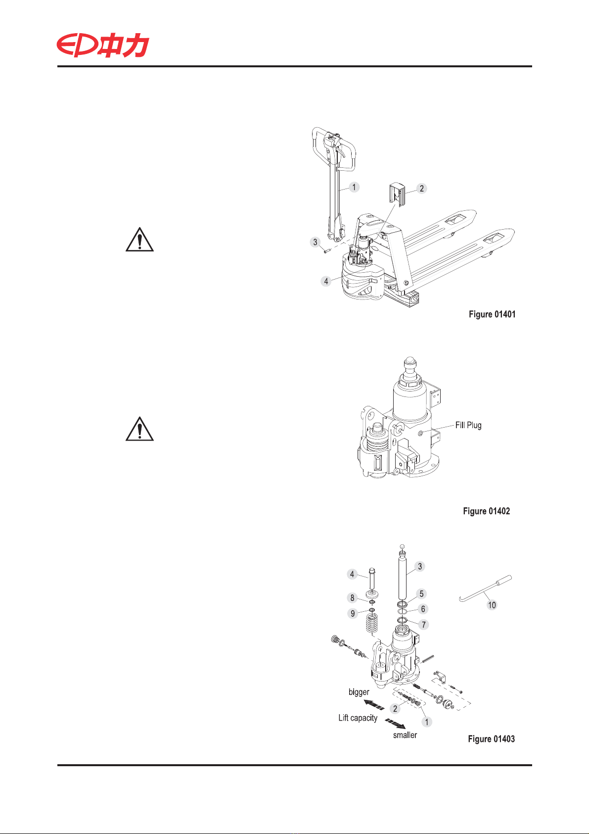
4. HYDRAULIC SYSTEM
Remove the handle (index 1) and the controller
(index 2).Remove the hydraulic assembly by
unscrewing the screw (index 3) and the four
screws (index 4).Place hardwood blocks under
the Frame as shown in Figure 01401.
The filler of hydraulic assembly is as shown in
Figure 01402.
Refer to Figure 01403. Change the lift capacity
by adjusting the position of the screw (index 2)
which is in the relief valve (index 1).
Screwing Inward = bigger
Screwing outward = smaller
The seal kit of hydraulic assembly includes
index 5,6,7,8&9.Pick out the piston rod (index 3)
and the pressure bar (index 4).Then the seals
are removed by using a hooked tool (index 10).
CAUTION
Put the hardwood block as neer the drive
wheel as possible.
CAUTION
It is filled with the 32# hydraulic oil.
4.1Disassembly and Assembly
Table of contents


 Operator's manual")

