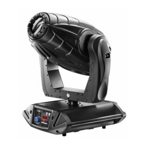
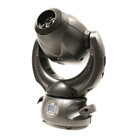
DTS A.R.C. User manual

Architectural lighting
PROGETTO GRAFICO DTS Show division
USER MANUAL
GB
A.r.c.
A.r.c.
A.r.c.
www.bluelight.at

INDEX
1- page. 4
2- page. 4
3- page. 5
4- page. 6
5- page. 6
6- page. 7
7- page. 9
9- CHANGING DMX ADDRESSES page. 9
10- DISPLAY PANEL OPERATION page. 10
11-
12- AUTOMATIC MODE page. 12
13- HIDDEN MENU page. 12
14- page. 13
15- DMX ADDRESSES page. 14
16 page. 17- ELECTRONIC CARD
TECHNICAL FEATURES
SAFETY INFORMATION
MOUNTING THE LAMPS
VOLTAGE AND FREQUENCY
INSTALLATION
MAINS CONNECTION
DMX SIGNAL CONNECTION
DISPLAY (disp) page. 11
PERIODIC CLEANING E CONTROL
370 mm 335 mm
475 mm
www.bluelight.at

1- TECHNICAL FEATURES
2- IMPORTANT SAFETY INFORMATION
Dmx colorchanger for architectural lighting internal or outdoor use ( Ip65)
Power supply
Power consumption:
Lamp:
Control:
Automatic mode
Linear dimmer
Shutte
Colours:
2 light beam angles (40° / 64°)
Working position: any position
Weight:
A.R.C.
A.R.C
: 230V 50-60 Hz
200 VA for CDM-T 150 lamp 300VA for MSD 250 lamp with in-built
factor correction
CDM-T 150 or MSD250 discharge lamp
4 channels DMX 512
8 dichroic filters with high chromatic yeld + white,
Different rotating speeds to produce RAINBOW effect.
15,5 kg
- uses a MSD250 or CDM-T 150 . The use of any alternative lamp is not
recommended and will null and void the fixture's warranty.
-Minimum distance from the closest illuminable surface: 0,5 m.
-Replace any blown or damaged fuses only with those of identical value. Refer to the wiring
diagram if there is any doubt.
-Connect the projector to mains power via a thermal magnetic circuit breaker.
-High voltage is present inside the unit. Isolate the projector from the mains supply prior to
performing any function which involves touching the inside of the unit, including lamp
replacement.
-The level of technology inherent in the . requires the assistance of specialised
personnel for all servicing. Refer all work to your authorised DTS service centre.
-A good earth connection is essential for proper functioning of the projector.
Never connect the unit without proper earth connection.
-Never turn the lamp on if the glass damaged. It respective shielding functions will only
operate efficiently if it is in perfect working order.
-Never look directly into the lamp when it is on.
2.1- Fire prevention:
2.2- Prevention of electric shock:
2.3- Protection against ultraviolet radiation:
r: strobe max 8 flash/sec
4
www.bluelight.at

2.4- Safety:
2.5- Level of protection against the penetration of solid and liquid matter
-The projector should always be installed with bolts, clamps and other fixtures that are
capable of supporting the weight of the unit.
-Always use a second safety chain of a suitable rating to sustain the weight of the unit in case
of the failure of the main fixing point.
-The external surface of the unit, at various points, may exceed 100°C. Never handle the unit
until at least 10 minutes have elapsed since the lamp was turned off.
-Always replace the lamp if any physical damage is evident.
-Never install the fixture in an enclosed area lacking sufficient air flow. The ambient
temperature should not exceed 35°C.
-A hot lamp may explode, so always wait for at least 10 minutes to elapse after the unit has
been turned off prior to attempting to replace the lamp.
Always wear suitable hand protection when handling the lamp.
-The projector is classified as an ordinary appliance and its level of protection against the
penetration of solid and liquid matter is IP 65.
The temperature inside the projector can reach 250° C after just 5 minutes, but it can get as
high as 350° C. Always check that the lamp is cold before attempting to remove it. In any
case, only open the appliance 10 minutes after it has been turned off.
1) Using a philips head screwdriver, remove the 3 screws placed on the rear end of the unit
so as to remove the lamp casing (photo 1).
2) Unscrew the three screws holding the lampsocket unit (photo2).
3) Remove the lampsocket unit and insert lamp in lampsocket (photo3).
3- MOUNTING THE LAMPS
WARNING: TURN POWER OFF BEFORE OPENING THE APPLIANCE.
Photo 1
Photo 2 Photo 3
5
www.bluelight.at

The lamp used is manufactured from quartz glass and should be handled with care. Always
adhere to the instructions supplied in the lamp's packaging. Never touch the glass directly but
use the tissue provided in the lamp's packaging. The Gy 9.5 lampbase (MSD250)is not
symmetrical; the G12 lampbase (CDM-T 150) is simmetrical.
. In case of difficulty, re-read the
instructions and repeat the procedure.
Attention: we recommend that the lamp be realigned in the optical train of the unit (Photo 4).
Alignment is carried out using the 3 adjusters.
During this operation you must bring the hot-spot to the centre of the beam and flatten it as
much as possible.
The projector can operate at 230V voltage, at 50-60Hz . D.T.S. presets a voltage of 230V at
a frequency of 50Hz (barring specific requests).
may be either floor or ceiling mounted.
For floor mounting installations, the is supplied with four rubber mounting feet (B)
on the base. For ceiling mounted installations, we suggest the use of appropriate clamps or
fixings to attach the fixture to the mounting surface.
Two holes situated at the base of the unit allow for the mounting of the unit with C clamps on
trussing.
DO NOT USE UNDUE FORCE ON THE GLASS
A.R.C.
A.R.C.
3.1 -Alignment lamp:
4 -VOLTAGE AND FREQUENCY
5 -INSTALLATION
Photo 4
6
INSTALLAZIONE A TERRA
INSTALLAZIONE A SOFFITTO
www.bluelight.at

5.1 -Safety chain
5.2 -Protection against liquids:
5.3 -Risk of fire:
5.4 -Ambient temperature:
We recommend the use of a safety cable or chain connected to the and to the
suspension truss in order to avoid the fixture accidentally falling should the main fixing point
fail. Make sure that the iron cable or chain can bear the weight of the entire unit.
The attachment of the safety chain is accomplished by passing it through the handles as seen
in the figure
The projector contains electric and electronic components which should under no
circumstances come into contact with oil, water or any other liquid. The proper working of
the unit would be compromised should this occur.
Each fixture produces heat and must be installed in a well-ventilated position.
Minimum distance from the object being illuminated is 0,5 m.
The projector should never be installed in places that lack a constant flow of air. The ambient
temperature should NOT exceed 35°C.
operates at voltage 230V at 50 or 60Hz. Connect power cable to internal clamp
connector (photo1-2).
Prior to connecting the unit to your mains supply, ensure that the model in your
possessioncorrectly matches the mains supply available. For connection purposes, ensure that
your plug is of a suitable rating of 5A at 230V. Strict adherence to regulatory norms is
A.R.C.
A.R.C.
6 -MAINS CONNECTION
7
Photo 2
Photo 1
LN
SAFTEY CHAIN
www.bluelight.at

Architectural lighting
strongly recommended.
The use of a thermal magnetic circuit breaker is recommended for each A.R.C..
A good earth connection is essential for the correct operation of the projector.
The unit operates using a digital DMX 512 (1990) signal. Connection between the control
box and the projector or between projectors must be carried out using a two pair screened
ø0.5 mm cable.
Connect the control box signal to the DMX IN internal connector clamp (found at the base of
the unit) and connect it to the next projector by connecting the DMX OUT connector clamp
on the first projector to the DMX IN connector clamp on the second.
In this way, all the projectors are cascade connected.
6.1 -Protection:
7- DMX SIGNAL CONNECTION
NB. If the letters A001 flash on the display the possible causes are:
- No DMX signal
- The DMX address not valid
- There is a DMX reception problem
- The number of channels sent out by the mixer is inferior to 24
If the letters A001 appear on the display without flashing the DMX signal is being received
and is valid.
8
A...
(2)DATA -
(3)DATA+
(1)GND
(3)DATA+
(1)GND
(2)DATA -
DMX512
IN
OUT
5
3
42
11=GND
2=DATA-
3=DATA+
CONTROLLER
STANDARD
DMX 512
IN
OUT OUT
IN OUT
IN
OUT
www.bluelight.at

8- DMX ADDRESSES:
A.R.C. To use 4 DMX channels.
Projector 1 A1
Projector 2 A11
Projector 3 A21
.....A...
Projector 6 A51
Projector 1 A1
Projector 2 A17
Projector 3 A33
....A...
Projector 6 A65
If you are using a DMX controller with 10 channels per projector set the following addresses
If you are using a DMX controller with 16 channels per projector set the following addresses
The address that has to be set on each projector generally depends on the number of channels that the DMX
mixer allots it.
If you have a 12 channel controller, set your to 10 CH MODE. The first projector will have an A001
address and if you want to select the next projector, then you have to add 12. The subsequent address will
then be A0013
A.R.C.
NB: The A.R.C. Needs a controller with at least 24 DMX channels to function properly.
For the next projector it is sufficient to add
.
“ 10”
“ 16”
9- CHANGING THE DMX ADDRESS
1) Press the UP-DOWN key until you reach the required DMX number. The numbers on the display will start
to flash (but the new DMX address hasn't yet been set).
2) Press ENTER to confirm your selection. The numbers on the display will stop flashing and the projector is
now controlled by the new 512 DMX number.
WARNING: if you press the UP-DOWN keys together the channels are calculated more quickly and you get
a faster selection
9
www.bluelight.at

10- DISPLAY FUNCTIONS
Using the display panel it is possible to add functions and to vary some of the units
parameters. Altering the DTS default settings could change the way the unit responds to the
inputs given by the DMX controller, therefore it is important that the following functions be
followed and understood before carring out any changes.
Please note: the symbol is used in the following table to indicate a button that must be
pushed.
10
ENTER ENTER UP-DOWN
UP-DOWN
UP-DOWN
ENTER
ENTER UP-DOWN
ENTER UP-DOWN
ENTER
ENTER
UP-DOWN ENTER
UP-DOWN
UP-DOWN
UP-DOWN
Menu
ENTER ENTER
UP-DOWN ENTER
COLOUR WHEEL SPEED
It is possible to change the speed
of the colour wheel, 18 different values
are available
UP-DOWN
UP
DOWN
ENTER
MENU
SETTINGS
MENU
ENTER
UP
DOWN
LED 1 LED 2
DISPLAY
Inverts the direction of display
depending on whether the unit
is placed upside down or upright
it also places the display in stand by mode.
TIMER
Lamp life display,
projector total running time.
reset of the lamp life
timer and
www.bluelight.at

11
UP-DOWN ENTER
UP-DOWN ENTER ENTER
UP-DOWN ENTER ENTER UP-DOWN
UP-DOWN
UP-DOWN
ENTER UP-DOWN
ENTER UP-DOWN
ENTER
ENTER
ENTER
UP-DOWN ENTER UP-DOWN ENTER
UP-DOWN ENTER
UP-DOWN ENTER
UP-DOWN ENTER
RESET
Resets both motors as well as
colour wheel and shutter.
Min.sec
UP-DOWN ENTER
11- DISPLAY (disp)
Using the menu it is possible to change the character direction of the display (POSI)
depending on whether you wish to mount the unit on the gorund our up-side down overhead.
It is also possible to activate the auto switch off (STBY) of the display after 3 minutes of
activity. However in standby mode a small red light will remain on indicating that the unit is
functioning, to reactivate the display it is sufficient to press any of the four buttons.
SOFTWARE VERSION
Circuit card software version check
DEFAULT
Reset to DTS defaults
AUTOMATIC
Automatic mode without DMX input, timer
mode and unit
activation on/off timer.
TEST MODE
Test mode for unit functions
www.bluelight.at
Table of contents
Other DTS Lighting Equipment manuals

DTS
DTS XR2000 BEAM User manual

DTS
DTS FOS 100 FULL RGBW User manual

DTS
DTS DOCTUS.D Series User manual

DTS
DTS Discharge Lamp 35-70-150W User manual

DTS
DTS NICK NRG1200 CT User manual

DTS
DTS XR5 SPOT User manual

DTS
DTS DELTA R FULL COLOR User manual

DTS
DTS Nick Wash 600 User manual

DTS
DTS Thomas & Betts NT 06 Manual

DTS
DTS PROFILO 500 User manual
Popular Lighting Equipment manuals by other brands

Qazqa
Qazqa Suplux SL 3 Black 103062 instruction manual

Commercial Electric
Commercial Electric 54568141 Use and care guide

CREE LIGHTING
CREE LIGHTING 304 Series installation instructions

Goobay
Goobay 49867 user manual

ECOMAN ITALIA
ECOMAN ITALIA LED T8 instruction manual

Alkalite
Alkalite Krypton KT-81 user manual