Dream Catcher ME3000 Analog Electronics Lab 6 User manual

http://dreamcatcher.asia/cw
______________________________________________________________________
ME3000 Analog Electronics Lab 6 - 1/19
ME3000 Analog Electronics
Lab 6
RF Class A Tuned Amplifiers
This courseware product contains scholarly and technical information and is protected by copyright
laws and international treaties. No part of this publication may be reproduced by any means, be it
transmitted, transcribed, photocopied, stored in a retrieval system, or translated into any language in
any form, without the prior written permission of Acehub Vista Sdn. Bhd.
The use of the courseware product and all other products developed and/or distributed by Acehub
Vista Sdn. Bhd. are subject to the applicable License Agreement.
For further information, see the Courseware Product License Agreement.
Objectives
i) To demonstrate the practical issues of designing an RF tuned amplifier
ii) To demonstrate AC measurements on a Class A amplifier
Equipment Required
i) ME3000-M2 Analog Electronics Training Kit
ii) Digital Multimeter, recommendation : Agilent 34405A or U2741A
iii) 50 MHz Oscilloscope or equivalent, recommendation : Agilent DSO1002A 60 MHz or
U2701A
iv) 10 MHz Function Generator or equivalent, recommendation : Agilent 33220A or U2761A
v) Dual Output (+/- 12V, 0.5A) DC Power Supply, recommendation : Agilent E3631A
Accessories Required
i) 1 x 4-way power supply cable
ii) 1 x BNC(m)-to-grabber clips coaxial cable
iii) 6 x jumper cables terminated with grabber clips at both ends
iv) 1 x antistatic wrist strap
Caution:
An electrostatic discharge generated by a person or an object coming in contact with electrical
components may damage or destroy the training kit. To avoid the risk of electrostatic discharge,
please wear the antistatic wrist strap and observe the handling precautions and recommendations
contained in the EN100015-1 standard. Do not connect or disconnect the device while it is being
energized.

http://dreamcatcher.asia/cw
______________________________________________________________________
ME3000 Analog Electronics Lab 6 - 2/19
1. Introduction
A Class A transistor amplifier is biased so that the transistor conducts continuously. The transistor of
the Class A amplifier is biased in the active region during the whole duration of operation. The Class A
amplifier is a linear amplifier since the transistor operation in the active region is almost linear. Two
types of amplifiers can be designed – tuned and untuned amplifiers. An untuned amplifier has a wider
bandwidth than a tuned amplifier, as shown in Figure 1.
A tuned amplifier consists of a resonance network as illustrated in Figure 2. It includes a parallel RLC
tank circuit. This circuit will experience high impedance and maximum voltage gain at the resonance
frequency. The resonance frequency can be calculated by LC
fo
2
1
.
R C L
Untuned amplifier
frequency response
Tuned amplifier
frequency response
Voltage
gain
Figure 1 – Class A Amplifier Frequency Response
Figure 2 – RLC Tank Circuit Schematic Diagram
Frequency
http://dreamcatcher.asia/cw
______________________________________________________________________
ME3000 Analog Electronics Lab 6 - 3/19
A radio frequency (RF) amplifier is designed to operate in the RF region which normally refers to
frequencies between 1 MHz to 300 MHz. Great care must be taken in designing an RF amplifier as
most of the components will not portray ideal characteristics at radio frequencies. Most of the RF
Class A amplifiers are tuned amplifiers to obtain higher voltage gain and be less susceptible to noise.
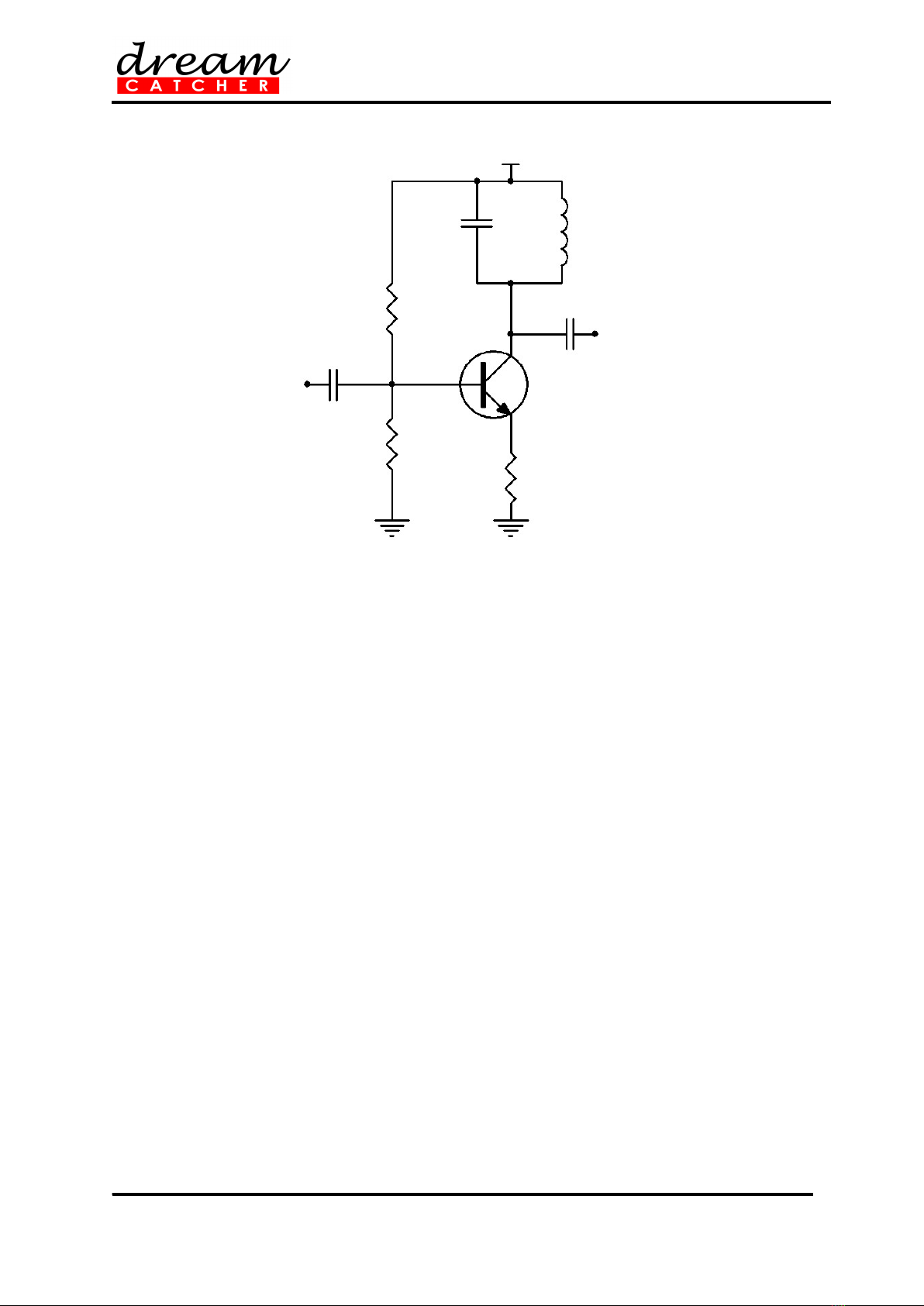
A typical RF Class A tuned amplifier is shown in Figure 3.
Vcc
Q
CC
C2
L
RB2
RE
C1
RB1
Input
Output
Figure 3 – Typical Class A Tuned Amplifier Schematic Diagram

http://dreamcatcher.asia/cw
______________________________________________________________________
ME3000 Analog Electronics Lab 6 - 4/19
2. DC Biasing
1. Locate the Class A Tuned Amplifier section on the ME3000-M1 training kit.
2. Disconnect all the jumpers located in the Class A Tuned Amplifier section.
3. Construct an RF Class A amplifier circuit shown in Figure 4 by connecting jumpers to J28 and
J29.
4. Connect the power supply to the training kit using the 4-way power supply cable. Set the
power supply voltage to +15 V. Turn on the power supply. Refer to Appendix for details.
5. Use the multimeter to measure VCC applied to the transistor (between terminals TP4 and
GND). Calculate the voltage at the transistor base using the resistive voltage divider formula,
CCB V
RR
R
V
1716
17
, where R17 = 4.7k and R16 = 10k. Then, calculate the voltage at the
transistor emitter, VE using VE = VB – 0.7.
6. Measure VC (at TP2 and GND), VB (at TP3 and GND), and VE (at TP5 and GND) on the
transistor C, B, E pins.
7. Verify that VB – VE ≈ 0.7 V.
8. Check if the calculated VB and VE values agree with the measured values.
9. Estimate IC using
E
E
EC R
V
II , where RE = R18 = 150 .
10. Determine the transconductance, gm of the transistor at T = 25 using
26
)(mAI
gC
m.
Vcc
Q3
C7
C8
L1
R17
R18
C6
R16
Input
Output
C10
R19
Figure 4 – Schematic Diagram of DC Biasing on an RF Class A Amplifier

http://dreamcatcher.asia/cw
______________________________________________________________________
ME3000 Analog Electronics Lab 6 - 5/19
3. Frequency Response
11. Set the function generator output to 40 mVpp.
12. Connect the function generator output to TP1 and reference to GND using the BNC-to-
grabber clips coaxial cable.
13. Connect the oscilloscope CH1 probe to TP1 and GND.
14. Connect the oscilloscope CH2 probe to TP6 and GND.
15. Set the trigger signal to CH1.
16. Sweep the function generator frequency from 2 MHz to 8 MHz in 100 kHz increments.
17. Record the peak-to-peak voltage at the input (CH 1) and output (CH 2), and determine the
magnitude of the voltage gain, AV as a function of frequency.
18. Plot the AV versus frequency curve and estimate the resonance frequency of the amplifier
from the curve. The input and output waveforms should be approximately 180 out of phase
during resonance. The voltage gain, AV is at its maximum when resonance occur, with the
theoretical resonance frequency given as LC
fo
2
1
, where L = 4.7 H and C = 100 pF.
19. Use the calculated AV at resonance to estimate the value of rCE using
m
V
m
V
L
L
ceLcemV g
A
g
A
R
R
rRrgA )||( .
20. Calculate the early voltage, VA of the transistor using
C
A
ce I
V
r.

http://dreamcatcher.asia/cw
______________________________________________________________________
ME3000 Analog Electronics Lab 6 - 6/19
4. Voltage Gain Estimation
21. Unplug the jumpers from J28 and J29.
22. Set RL = 470 by connecting jumpers to J30 and J31.
23. Set the function generator output to 40 mVpp and the output frequency to the resonance
frequency value measured earlier.
24. Connect the function generator output to TP1 and reference to GND.
25. Connect the oscilloscope CH1 to TP1 and GND.
26. Connect the oscilloscope CH2 to TP6 and GND.
27. Set the trigger signal to CH1.
28. Record the peak-to-peak voltage at the input (CH 1) and output (CH 2), and determine the
magnitude of the voltage gain, AV.
29. Determine the amplifier voltage gain using )||( LcemV RrgA and the rce and gm values
calculated earlier. Compare the calculated value with the value measured in step 28.
30. Repeat steps 28 and 29 for RL = 1470 by unplugging the jumpers from J30 and J31 and
connecting the jumpers to J28 and J32.
31. Turn off the power supply and disconnect all the cables from the Class A Tuned Amplifier
section.

http://dreamcatcher.asia/cw
______________________________________________________________________
ME3000 Analog Electronics Lab 6 - 7/19
Appendix: Tips on Using Agilent E3631A Triple
Output DC Power Supply
Supplying +5 V, +15 V, and 15 V to the ME3000-M1 training kit:
Press Power to turn on the E3631A.
The E3631A has three adjustable output supplies namely +6 V, +25 V, and 25 V. By default,
all outputs are disabled (the OFF annunciator is turned on), the +6 V supply is selected, and
the knob is ready for voltage control.
Adjust the knob to +5 V.
Press Display Limit and set the current limit to 0.5 A.
Next, set the supply to +25 V (positive supply). Set the voltage to +15 V and current limit to
0.5 A. Repeat the same procedure for –25 V (negative supply) to set the voltage to 15 V and
current limit to 0.5 A.
Connect the E3631A to the ME3000 training kit as shown below.
Enable the power supply outputs by pressing Output On/Off. The CV and +25 V
annunciators should turn on.
Caution: If the CC annunciator is turned on, disable the output and check whether this is due
to the current limit setting or faulty connection.
Upon completion of each experiment and before making any connection on the training kit,
ensure that the power supply output is disabled by pressing Output On/Off.
ME3000-M1 Training Kit
Power Supply
(E3631A)
com
–
+
25 V
6 V
–
+
4-way
connector

http://dreamcatcher.asia/cw
______________________________________________________________________
ME3000 Analog Electronics Lab 6 - 8/19
Appendix: Tips on How to Use the Agilent U2741A
USB Modular Digital Multimeter
Front Panel of the Agilent U2741A USB Modular Digital Multimeter
Figure B-1 – Front Panel of the Digital Multimeter
Setting Up the Connection
1. Connect the digital multimeter to the PC using a USB cable.
2. Power on the digital multimeter.
3. Launch the Agilent IO Control and the Agilent Measurement Manager (AMM).
4. The Select USB Device dialog box will appear displaying the connected U2741A devices. To
start the application, select a U2741A device and click OK to establish the connection
5. The U2741A can only be operated via the USB interface. On the front panel of the U2741A,
there are two LED indicators. The power indicator lights up once the U2741A is powered on.
There is a system error if the indicator blinks after the U2741A is powered on. The USB
indicator will only blink when there is data exchange activity between the U2741A and the PC.
6. You can control the U2741A via the Agilent Measurement Manager (AMM) for U2741A or
via SCPI commands sent through the USB interface from your own application programs.
7. Launch the Agilent IO Control and AMM.
8. The Select USB Device dialog box will appear displaying the connected U2741A devices. To
start the application, select a U2741A device and click OK to establish the connection. You
may start to use the digital multimeter now.
Measuring DC Voltage
1. The DC voltage measurement function of the U2741A has the following features:
five ranges to select: 100 mV, 1 V, 10 V, 100 V, and 300 V; or auto range
input impedance is 10 MΩ for all ranges (typical)
input protection is 300 V on all ranges (HI terminal)

http://dreamcatcher.asia/cw
______________________________________________________________________
ME3000 Analog Electronics Lab 6 - 9/19
2. Make the connection as shown in Figure B-2 in order to measure DC voltage. You can
control the U2741A via the Agilent Measurement Manager (AMM) software for U2741A or
via SCPI commands sent through the USB interface from your own application programs.
Figure B-2 – Measuring DC Voltage
3. If you are using the AMM, select the DCV function located at the top-left corner. Set the
desired range under Range section. A suitable range should be selected to give the best
measurement resolution. The reading is displayed and updated continuously.
4. If you are using SCPI commands, enter MEASure[:VOLTage]:DC? in order to make a DC
voltage measurement.
Measuring DC Current
1. The DC current measurement function of the U2741A has the following features:
three ranges to select: 10 mA, 100 mA, 1 A, and 2 A; or auto range
input impedance is 10 MΩ for all ranges (typical)
input protection fuse is 2 A, voltage rating 250 V on all ranges
2. Make the connection as shown in Figure in order to measure DC current. You can control
the U2741A via the Agilent Measurement Manager (AMM) software for U2741A or via SCPI
commands sent through the USB interface from your own application programs.
Figure B-3 – Measuring DC Current
3. If you are using the AMM, select the DCI function located at the top-left corner. Set the
desired range under the Range section. A suitable range should be selected to give the best
measurement resolution. The reading is displayed and updated continuously.
4. If you are using SCPI commands, enter MEASure:CURRent[:DC]? in order to make a DC
current measurement.

http://dreamcatcher.asia/cw
______________________________________________________________________
ME3000 Analog Electronics Lab 6 - 10/19
Appendix: Tips on How to Use the Agilent
U2761A USB Modular Function Generator
Front Panel of the Agilent U2761A USB Modular Function Generator
Figure A-1 – Front Panel of the U2761A
Setup Connection
9. Connect the function generator to the PC using a USB cable.
10. Power on the function generator.
11. Launch the Agilent IO Control and the Agilent Measurement Manager (AMM).
12. The Select USB Device dialog box will appear displaying the connected U2761A devices. To
start the application, select a U2761A device and click OK to establish the connection.
13. Click Output to enable or disable the output of the function generator after the desired
parameters are set.
14. The U2761A is able to output five standard waveforms that are Sine, Square, Ramp,
Triangle, Pulse, and DC.
15. You can select one of the three built-in Arbitrary waveforms or create your own custom
waveforms.
16. You can also internally modulate Sine, Square, Ramp, Triangle, and Arbitrary waveforms
using AM, FM, PM, FSK, PSK, or ASK.
17. The linear or logarithmic frequency sweeping is available for Sine, Square, Ramp, Triangle,
and Arbitrary waveforms.
18. Table A- shows which output functions are allowed with modulation and sweep.
19. Each √ indicates a valid combination. If you change to a function that is not applicable for
modulation, or sweep; then the modulation or mode will be disabled.
Table A-1 – Output Functions
Sine Square Ramp Triangle Pulse DC Arbitrary
AM, FM, PM, FSK, PSK, ASK Carrier √ √ √ √ √
AM, FM, PM Internal Modulation √ √ √ √ √
FSK, PSK, ASK Internal Modulation √
Sweep Mode √ √ √ √ √
Table of contents


