dooch NSQ Series User manual

NSQP
HNSQP
BOOSTER PUMP SYSTEM
PREMIUM


CONTENTS
3
Cause of Fault and Reaction
Basics
Safety Instruction
Features of Product
Components of Product
Method of Operation
Installation
Inspection and Maintenance
Drive
- Control mode
- Method of pressure setting
- Parameter Mode
- Pr (Pump) - dr(Drive)
- Fault History Table
- Measures be taken in case of
fault or alarm
- Internet Modem
- RS-485
Communication(Option)

Basics
Manifold Size
Pump Model
Each of Pump
Inverter Type
In-Line type manifold
H NSQ 3 DRL 10-6 - 80A
NSQ-Drive
Exclusive Inverter for Pump
Power Range : 0.75~22kW
Input Power : 1Φ×200~230V (0.75~2.2kW)
3Φ×380~440V (0.75~22kW)
Output Power : 3Φ×380V
Frequency : 50/60Hz
Model
Feature
Specification
H Without H
In-Line Type Manifold Standard Type Manifold

Warning
Caution
Safety Instructions
Preface
Thank you for choosing DOOCH’s high performance NSQ-Drive series.
Describing specification, installation, operation, function, and maintenance of the NSQ-Drive
series provided for the users who are familiar with and having basic experience in using a
variable frequency drive.
Be sure to understand function, performance, installation, and operation of the product by
reading through this User's Manual completely prior to your use of NSQ-Drive series that
you have purchased. In addition, you are required to have this User's Manual properly
delivered to the end-user and maintenance manager.
Safety Precautions
Remark
To prevent injury and property damage, follow these instructions. Incorrect operation
due to ignoring instructions will cause harm or damage.
The seriousness of which is indicated by the following symbols.
Even if the instructions are indicated as ‘Caution’, it can cause a serious result according to the kind
of operation and the environment.
The meaning of each symbol in this manual and on your equipment is as follows.
Warning :
This symbol indicates the possibility of death or serious injury.
Caution :
This symbol indicates the possibility of injury or damage to property.

Do not remove the cover while power is applied or the unit is in operation.
Otherwise, electric shock could occur.
Do not run the inverter with the front cover removed.
Otherwise, you may get an electric shock due to high voltage terminals or
charged capacitor exposure.
Do not remove the cover except for periodic inspections or wiring, even if
the input power is not applied.
Otherwise, you may access the charged circuits and get an electric shock.
Wiring and periodic inspections should be performed at least 10 minutes
after disconnecting and after checking the DC link voltage is discharged
with a meter (below DC 30V).
Otherwise, you may get an electric shock.
Operate the switches with dry hands.
Otherwise, you may get an electric shock.
Do not use the cable when its insulating tube is damaged.
Otherwise, you may get an electric shock.
Do not subject the cables to scratches, excessive stress, heavy loads or
pinching.
Otherwise, you may get an electric shock.
Install the VFD on a non-flammable surface. Do not place flammable
material nearby.
Otherwise, fire could occur.
Disconnect immediately the input power if the inverter gets damaged.
Otherwise, it could result in a secondary accident and fire.
After the input power is applied or removed, the VFDwill remain hot for
a couple of minutes.
Otherwise, you may get bodily injuries such as skin-burn or damage.
Do not apply power to a damaged inverter or to the VFD with parts missing
even if the installation
Otherwise, electric shock could occur.
Do not allow lint, paper, wood chips, dust, metallic chips or other foreign
matter into the drive.
Otherwise, fire or accident could occur.
Caution
Warning
Safety Instructions

Safety Instructions
Cautions for Use
A. Transportation and Installation
Be sure to carry VFD in a proper way suitable for its weight, or it may result in damage to the VFD.
Be sure to use heat-treated wooden crate when you adopt wooden packaging for the product.
Do not pile up VFD's above allowable limit.
Be sure to install the VFD as directed in this instruction manual.
Do not turn off the power supply to the damaged VFD.
Do not open the front cover while carrying the VFD.
Do not place the heavy material on the VFD.
The direction of installation should be observed properly as criterions specified in this manual show.
Make sure that you should not put screw, metal material, water, oil and the inflammable something else.
Keep in mind that the VFD is very vulnerable to drop from the mid air and strong shock.
Don't let the inverter exposed to rain, snow, fog, dust, etc.
Do not cover, nor block, the ventilating system having cooling fan. It may cause the VFD overheated.
Be sure to check the power is off when installing the VFD.
To prevent the risk of fire or electric shock, keep the connected wire in a sound condition.
Use the wire that meets the standard in a recommended length.
B. Wiring
A professional installer should have done the wiring and checking.
Do wiring after installing the VFD body.
Do not connect phase-leading capacitors, surge filter, radio noise filter to the output of the VFD.
Output terminals (terminals named U, V, W respectively) should be connected in a proper phase
sequence.
Make sure that there is not any short circuit terminal, wrong wiring. It may cause spurious operation
or failure.
Refrain from using a cable other than the cable shielded when you connect control circuit wiring.
Adopt the shielded wire only when wiring the control circuit. It may cause the failure of the VFD in its
operation.
Use the twisted pair shield wire for the ground terminal of the VFD
Installation Location Free of corrosive gas, inflammable gas, oil sludge and dust, etc
Temperature/Humidity -10 ~ 40℃/ Below 90% RH (Dewdrop should not be formed)
Storage Temperature -20~65℃
Elevation/Vibration Altitude 1,000m or lower / below 5.9m/sec²(=0.6g)
Ambient Atmospheric Pressure 70~106 kpa

Features of Product
Apply advanced technology of new booster system
Minimize pressure fluctuation by durable multi inverter
Optomized design with controller module
RS-485 comm., Ethernet and Internet remote control (OPTION)
PID Control by Micro Processor
Sequential pump run and stop
Running stop and fault when low water level
If one of the pump is out of order, another pump operate.
If the motor is over current, the trip is occured automatically.
Pump operate throughout owner-operation
High Pressure Alarm level
Low Pressure Alarm level
Correct the sensor value if the sensor value differ from analogye value
Save all of run history of pump
Save all of the trip and error history of pump
all pumps have evenly run time.
The pump operate individually
Input muti-functional external analogue
After calculating the intergrated curent from each controller, disribute the current to all pump.
RS485communication
IM2000 Internet modem
Functions
PID controller
Sequential Operation
Dry-running protection
Fault pump Skip
Motor Overcurrent Protection
Owner -Operation
High Pressure Alarm
Low Pressure Alarm
Revised sensor value
Run History
Trip History
Relief operation
Intergrated current operation
Contact each of pump
Input external analogue
485comm.(option)
Internet modem(option)
Fixed Hz Operate When the pressure sensor is out of order, pump can operate fixed Hz
Explanation

System Component
Product Component
Panel
Inverter
Controller
Pump
Bed
Manifold-Suction
Manifold-Discharge
Pressure Transmitter
Suction Isolating Valve
Check Valve
Pressure Tank
No.
2
1
3
4
5
6
7
8
9
10
Discription
1
2~6
2~6
2~6
1
1
1
1
1/PUMP
1/PUMP
1
Quantity
4 ~ 20mA
-
-
-
-
-
Standard Manifold
Standard Manifold
-
-
Depend on pump size
Comments
2
7
9
6
5
3
1
4
8
NSQP Booster Pump
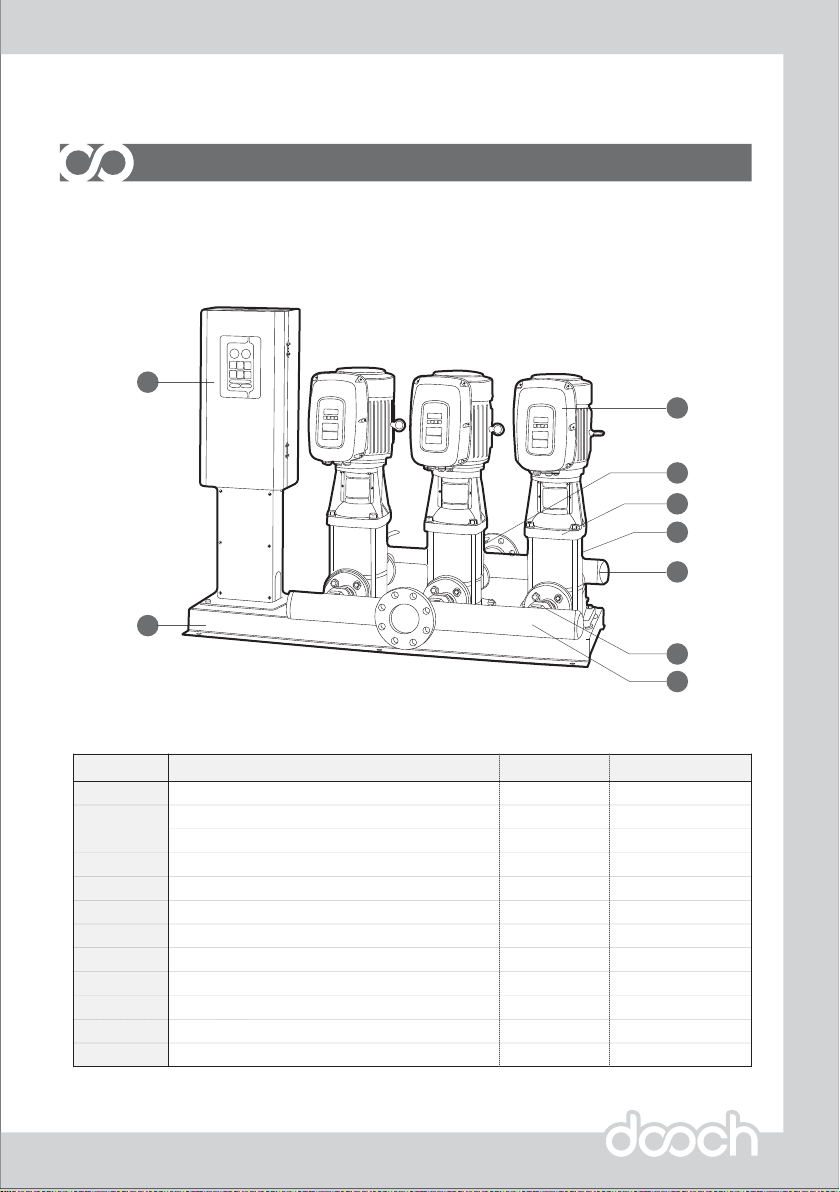
Panel
Inverter
Controller
Pump
Bed
Manifold-Suction
Manifold-Discharge
Pressure Transmitter
Suction Isolating Valve
Check Valve
Air Vent
No.
2
1
3
4
5
6
7
8
9
10
Description
1
2~6
2~6
2~6
1
1
1
1
1/Pump
1/Pump
1
Quantity
4 ~ 20mA
-
-
-
-
-
In-Line Manifold
-
-
-
Pressure Tank11 1Depend on pump size
Comments
HNSQP Booster Pump
2
7
8
5
6
3
1
4
9
Product Component
System Component
In-Line Manifold
This manual suits for next models
1
Table of contents
Other dooch Water Pump manuals

Popular Water Pump manuals by other brands


Sykes AmeriPumps
Sykes AmeriPumps GP100M Operation and maintenance instructions

DUROMAX
DUROMAX XP WX Series user manual

BRINKMANN PUMPS
BRINKMANN PUMPS SBF550 operating instructions

Franklin Electric
Franklin Electric IPS Installation & operation manual

Xylem
Xylem e-1532 Series instruction manual

Milton Roy
Milton Roy PRIMEROYAL instruction manual