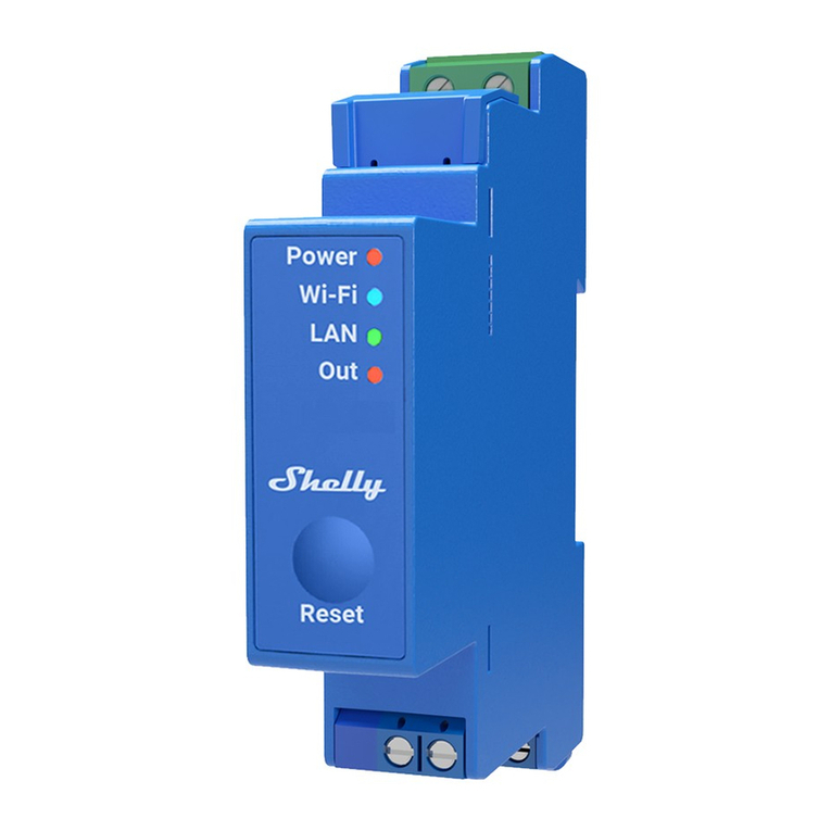
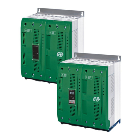
Digital Loggers DIN Relay 4 User manual

Web Controlled
DIN Relay 4
USER’S GUIDE V1.4

1DIN RELAY 4 Digital-Loggers.com
2
Standard Features
Congratulations on your purchase. The DIN relay is an
industrial Ethernet controlled relay with these features:
Web Interface, Keypad and LCD
The internal web server is accessible from any standard
web browser. Enter an IP to congure and control via the
http, or use the keypad and LCD for local control.
8 SPDT Relay Outputs
Eight sets of single-pole double-throw contacts are provided.
Screw terminals are pluggable. Recommended current is
10A at 120VAC. Relays are fused at 12A. Heavy silver
plated contacts are used for durability.
Power Input
The switching power supply accepts 12-28 VDC and draws
5W maximum.
Security: Password, HTTP Port and Subnet Restriction
Password security and a changeable HTTP port help
control access. Subnet restriction limits control to your LAN.
Multiple users are supported with individual relay masking.
Sequenced “On Timer”
A programmable delay timer allows relays to be switched on
in sequence, rather than simultaneously. Many loads draw
more power when they are initially switched on. Sequencing
prevents circuit overloads when loads devices are attached
to a single circuit.
Scripting, AutoPing, and FLASH Firmware Upgrades
The Lua scripting language provides simple PLC function-
ality. Modify the sample scripts or write your own. Learn
more at
www.lua.org
AutoPing monitors and reboots
routers, servers and IP gear automatically. FLASH rmware
is upgradable via local hardwired Ethernet.
Mounting Rails
The DIN relay mounts on standard 35mm rail. Call us at
(408) 330-5599 if you need a piece cut to length. To mount
directly on a panel, use #6 screws on 5.8 x 3.9" centers.

DIN RELAY 4 3
Maximum Terminal Torque
Use stranded wire only. Torque terminals to 20in-lbs max.
Important Factory Defaults
DEFAULT IP ADDRESS AND LOGIN
The factory default IP address is 192.168.0.100
User name: admin (lower case)
Password: 1234
RESET PROCEDURE
You may want to take a backup of your settings rst. To
reset to default, gently depress the reset switch with a
stylus and select a reset option.
The display displays an overview of possible actions.
Interrupt it by pressing UP/DOWN or CYCLE..
Use UP/DOWN to select a reset mode. The selected
mode is displayed on the second LCD line. Available
modes are:
• Clear lock bits
• Reset Network and Scripting
• Reset Network & Scripting, plus Enable WiFi
• Complete wipe: - All settings will be lost
• Complete wipe + Enable WiFi!
Note: The last two 'wipe' modes enable the Subnet
Restriction. ONLY MACHINES IN THE SAME SUBNET
WILL BE ABLE TO CONNECT AFTER RESET. If
connectivity is lost, you may use a local connection
such as a laptop to restore your original network
settings.
Quick Setup
Use these shortcuts for a quick installation:
1. Connect using an RJ-45 cable. Make sure the
192.168.0.100 IP is compatible with your LAN.

1DIN RELAY 4 Digital-Loggers.com
4
2. Apply power to the relay. The LCD will illuminate.
3. Enter 192.168.0.100 in your web browser address bar.
If the login page doesn’t appear, follow the IP Setup
instructions.
4. Login using the default user name, admin (lower case).
Enter the default password, 1234
5. Use the setup page to add relay names or change the IP.
6. ImportantSet the recovery mode for safety after a power
failure. The recovery mode controls default relay settings
after power is restored.
7. Change the password to improve security.
Tip: An ohmmeter is handy for testing the relay before
attaching equipment.
IP Setup
If your network settings won’t access the default IP, use a
direct cable connection (temporarily bypass any switch or
router) and follow these steps to add a compatible IP such
as 192.168.0.50 Before adding an IP, close programs and
browsers. After the link is established, you can revert to
DHCP or use a combination of DHCP and static IPs.
Windows Step 1
In Windows, the rst step to changing IPs is locating the
network adapter TCP/IP properties. The procedure diers
for each version of Windows:
Windows XP, 2000, 2003: Open Start / Control Panel
/ Network Connections. If you’re using “classic view”, it’s
Start / Settings / Control Panel /Network Connections.
Right-click on Local Area Network Connection and
select Properties. Proceed to step 2.
Windows Vista: Open Start, right click on Network,
then on Properties. Double click Network and Sharing
Center, click Manage Newtork Connections. A Network
Connections window appears. Right click on the network
connection to the switch, ie. Local Area Network.
Proceed to step 2.

DIN RELAY 4 5
Windows 7: Use the default Category View. Open
the Start orb, click on Control Panel. Click View
Network Status and Tasks, then Change Adapter
Settings. Proceed to step 2.
Windows 8/10: Mouse or swipe to the bottom right
corner and select Settings. Select Control Panel.
Select Network and Sharing Center. Change Adapter
Settings. Right click on your connected network and
select Properties. Proceed to step 2.
Windows Step 2
The second step is adding an IP such as 192.168.0.50.
If you are using DHCP, it’s easiest to temporarily
disable it while conguring the relay.
Select Internet Protocall TCP/IP V4 Properties and
click Properties. Enter a compatible static IP. Click
Apply and close windows. Ping the relay to conrm.
Point your browser to 192.168.0.100 Log in.
Max OS X IP Setup
Turn AirPort o temporarily. Click the Apple logo, then
System Preferences, then Network. Select Built-In
Ethernet and then Congure. Under the TCP/IP tab,
select Manually and enter an IP address such as
192.168.0.50

1DIN RELAY 4 Digital-Loggers.com
6
Basic Operation
After initial power-up, the relay performs a sequence of self-
tests (POST) to ensure reliability. After self-test, the relay
looks for a DHCP server. If none is found, the relay defaults
to the xed (static) IP address set on the setup page.
This is shown on the LCD. If enabled, script execution
starts after POST. The relay may then be operated via the
web. To access the relay, simply enter the IP address (ie.
192.168.0.100) in the URL eld of your web browser.
Home Relay (Relay) Control Page
To access the home page, rst enter the IP address in web
browser URL eld, then log in. The home page contains links
to other pages. The rst four are static internal links:
Relay Control
Clicking “Relay Control” links to the home page used for
manually switching relays on and o. Access masking to
specic relays is determined by your login.
Settings
Clicking “Settings” links the administrator to a conguration
page. This page is used to set relay names, power on
features, network settings, user information and passwords.
Help
The Help link displays the latest online manual. Since
features are subject to change without notice, online
manuals are usually more current than printed manuals.
Logout
Logout ends the authenticated session. Login to reconnect.
Programmable Web Links
Four additional user-dened web links are provided on the
relay control page. Factory defaults are “Manual”, “FAQs”,
etc. You may change the name and destination URL for
these links on the “Setup” page. These links are convenient
for connecting to other power switches or to remote sites.
Switching Relays on and O
The relay control page lets you control any relay. The
sequence delay in which relays will be switched on is
determined by settings on the setup page.

DIN RELAY 4 7
To switch a relay on or o, simply click to the right of
the relay name or number. Switching is immediate. You
may also “Cycle” an attached device. This is useful for
rebooting devices which may interrupt the network link to
the relay. Clicking “Cycle” switches power o, waits a few
seconds (as specied by the sequence delay), and then
switches power back on. You may also “cycle” all relays
via the “Cycle all relays” button.
Most browsers have an internal setting for maximum
refresh rate. Depending on your web browser settings,
you may need to click the “refresh” button to update the
on-screen status display after changes.
Setup Page
These settings congure the relay. Only admin has
access.
Switch and Relay Names
Use the switch name eld to assign a Switch Name to the
power relay itself. Examples are “Machine Tool Controls”
or “Lighting Relay”. The Switch Name eld appears on the
top of the home page. Assign an identifying name to each
load, such as “Sump Pump” or “Email Server”.
Power-On Sequence Delay
When a time value is entered in the “All ON sequence
delay” eld, the power relay will pause for a period of time
before energizing each relay on in sequence. This delay
can prevent the power surges and blown circuit breakers
which can occur when multiple loads are switched on
simultaneously. A delay of 60-120 seconds is typical.
You may also enter a screen refresh delay. If “Enable
screen refresh” is checked, and a delay value is entered,
your browser should periodically update the status screen.
The maximum update rate is limited by browser settings.

1DIN RELAY 4 Digital-Loggers.com
8
Power Loss Recovery Modes
The power loss recovery mode setting has three setting
options which take eect after every power failure:
1. You can turn all relays o (all relays stay switched o until
manually turned on later) by checking the rst box.
2. You can automatically turn all relays on using the “All ON
sequence delay” described above. Check the second
option to do this.
3. You can return to the same relay settings that were used
prior to the power loss. The “All ON sequence delay” will
also be used in this instance.
A script starting on power-up may override these settings.
User Dened Links
You may link to other power relays, your own web pages,
or remote web sites by entering up to four URLs and
descriptions in the Setup page. For example, enter “Site
Two Power Switch” in the description eld with a URL of
“192.168.0.102” These links appear in a left column.
Conrm Option Checkbox
Checking “Conrm” causes the web server to issue a
conrmation dialog box before accepting any on/o change.
Adding Users
Only the admin may add users and passwords. Each user
may control certain relays using the masking matrix. It is
possible (but not recommended) to add a user without a
password. This will allow unauthenticated access to selected
relays. Only non-admin user web pages are scaled for
mobile devices.
Network Settings
A xed IP address, network mask, gateway, and subnet
mask must be entered in this eld. To lock these settings,
click the “protect” button. This blocks changes until the
hardware reset button in the lower left corner is pressed.

DIN RELAY 4 9
When changing IP addresses, you may need to restart
your network switch to validate the new IP on an “auto-
conguring” switch port. Be sure to record the new IP
address.
Auto Ping Automatic Reboot
The internal AutoPing™ feature is a handy system for
rebooting IP equipment without human intervention.
AutoPing works by cycling power when a device becomes
unresponsive to IP pings. To learn more about AutoPing and
how to use it, visit: Digital-Loggers.com/AutoPing2.html
Security
Your relay employs secure challenge-response
authentication,and HTTPS with a new encryption token for
each transaction. This gives it fairly good out-of-the box
security. Making it more secure takes just a moment:
Changing the Password
It’s a good idea to change your password. You will be
prompted to change it from the default. Use the Setup page
to change it. Write it down in a safe place.
Restricting Subnet Access
To restrict access to only the 255 IP addresses on your LAN,
“Class C”, enable the subnet restriction on the setup page.
Changing the HTTP Port
Changing the HTTP port to a non-standard value makes
it more dicult to nd the relay. The default port is
80. For example, if you change the port to 5372, use
http://192.168.0.100:5372 to access the relay.
HTTPS
Recommended for security, but can be disabled by admin.

1DIN RELAY 4 Digital-Loggers.com
10
Installing Inside a Firewall
Install your relay inside a rewall (using port forwarding), rather
than directly on the Internet for an additional layer of security
Power Input and Consumption
Your relay can be powered from an external DC supply as
low as 12VDC and as high as 28V. Do not exceed 28VDC.
At 33V, an SCR crowbar will shut down the relay to protect it.
Disconnect the relay, eliminate the source of high voltage and
allow the relay to cool. It will then self-reset.
The relay contacts are fully isolated (1KV hipot tested) from the
power supply.
Maximum relay power dissipation occurs at 11V DC.
Undervoltage lockout occurs at approximately 10.2V with 1.5V
hysteresis. Current drain decreases with input voltage due to
the use of a bucking regulator. The lowest power consumption
occurs at idle, approximately 2W. With all relays energized,
power consumption increases to approximately 5W. Although
the case is well ventilated, ambient air temperature should not
exceed 150F for maximum reliability. Add an external MOV
or other protection device across the power input terminals in
noisy environments.
Relay State DC Volts I (A) Power (W)
All OFF 10.3 UVLO Lockout
All OFF 11.5 0.180 Startup 2.0W
All OFF 28 0.085 2.0
All ON 12 0.41 4.90
All ON 28 0.37 4.6
All OFF 33 -- Shutdown
Ethernet Link Status
The LCD now provides Ethernet cable connection status.
LEDs are no longer present on the Ethernet connector.
Table of contents