Deutschmann Automation GmbH & Co. KG
15.08.2012 Description Developerkit UNIGATE®FC V1.0 7
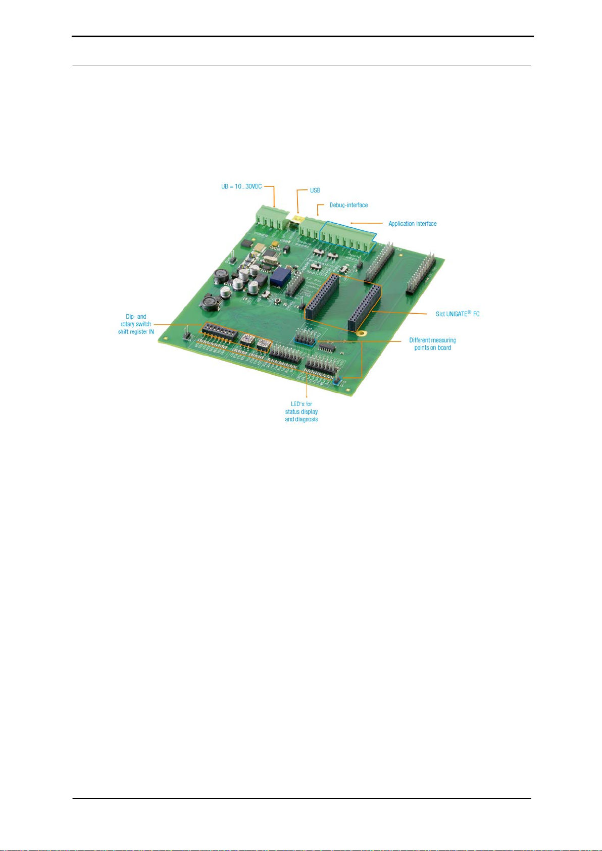
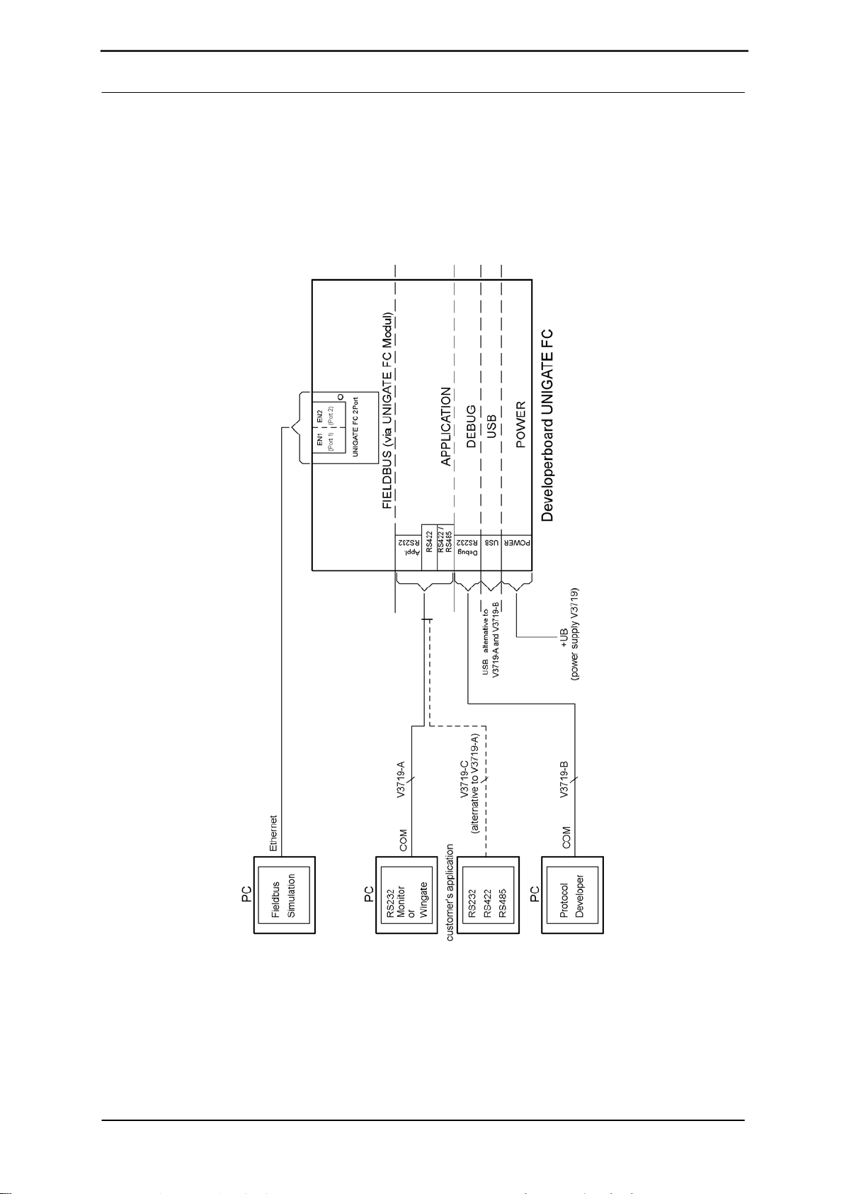
5. Overview Developerboard UNIGATE®FC:
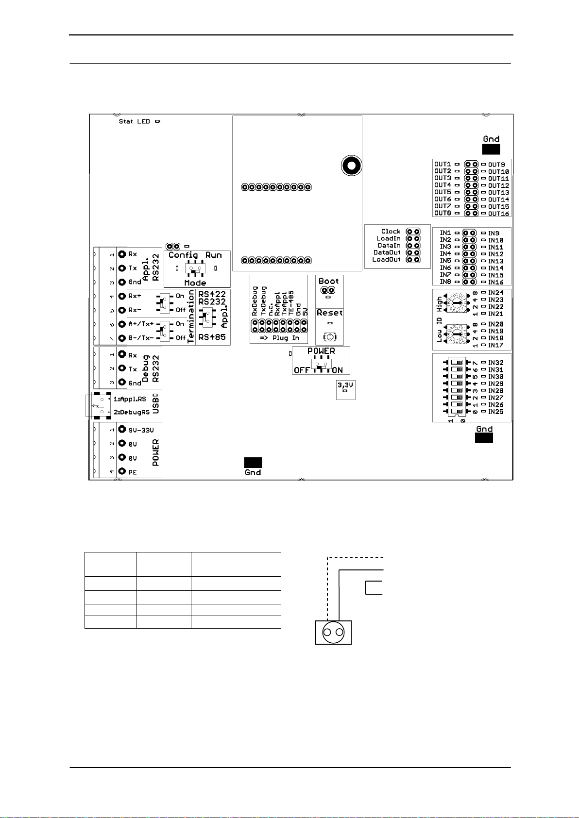
Slot UNIGATE®FC:
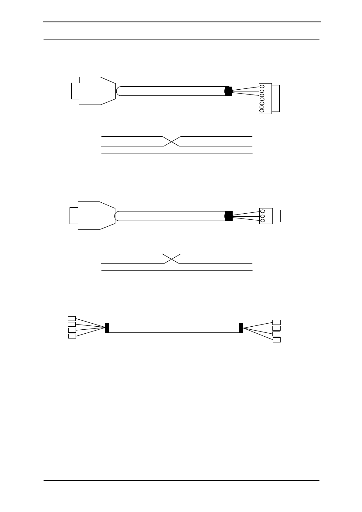
Note the direction. RJ45-socket of the UG-FC module
in direction of the edge of
the board.
ATTENTION: The UNIGATE®FC must never be inserted the wrong way
into the socket!
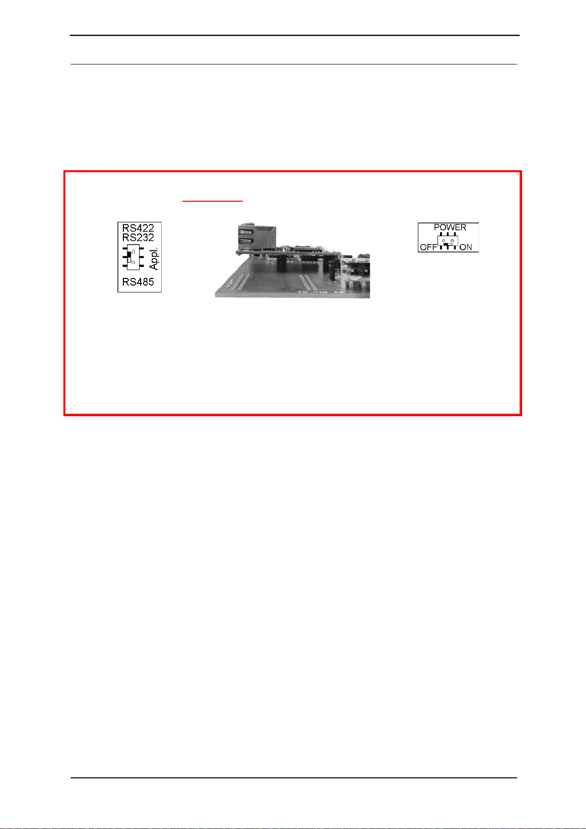
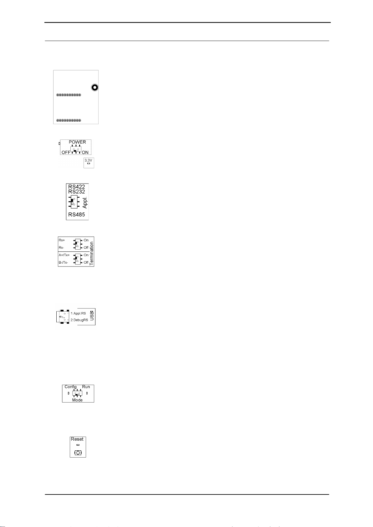
Sliding switch POWER ON/OFF and 3,3V-LED:
At Power ON the POWER-LED and the 3.3V-LED are illuminated.
Slide switch Appl. RS422, RS232/RS485:
This switch is required for setting of the serial (application) interface. The
switch can be used to switch between a RS422 and a RS485 interface. This is
the interface upon which the customer equipment is connected.
Sliding switch termination Appl. RS422/RS485:
Both of these switches are only relevant when the application interface is an
RS422 or RS485. Then the termination of the RS422 (both switches) or the
RS485 Bus (lower switch) can be connected via these switches.
USB pin-and-socket connector:
The board is connected to the PC via this plug-in connector. Thus, access is
provided to the 2 series interfaces (Appl. RS232 and Debug RS232) via 2 virtual
COM interfaces. A status LED indicates the USB connection.
Installation USB Driver [Support CD]: \Support\USB\Driver:
Two additional COM ports are available on your PC after installation. One port is
connected with the application interface, the other with the board’s debug
interface.
NOTE: the external supply (e.g. power supply unit V3719) is imperative
Supply via USB is insufficient.
Sliding switch mode Config/Run:
The UNIGATE®FC starts in configuration mode when set in “Config” position
during the PowerUp or Reset.
The “Run” position is the normal operating mode in which the UNIGATE®FC
runs the imported Script. An LED indicates the respectively set mode.
NOTE: In order to be able to use the configuration mode with the
software tools from Deutschmann, the PC must be connected with the
Reset key:
A UNIGATE®FC reset is activated by pressing the reset key.
The red reset LED lights up each time the key is pressed.