
Desert Star PILOT User manual

PILOT™
Precision Underwater Acoustic Positioning System
Operator’s Manual
Version 4.1
March 2007
Desert Star Systems, LLC
3261 Imjin · Marina, CA 93933
(831) 384-8000 (831) 384-8062 FAX

www.desertstar.com
© Copyright 2007, Desert Star Systems
PILOT Quick Reference Card
PILOT COMPONENT
FUNCTION
Surface Station Box (STM-1 or STM-10)
Serves as the junction between Sonar
Transducers and the PC.
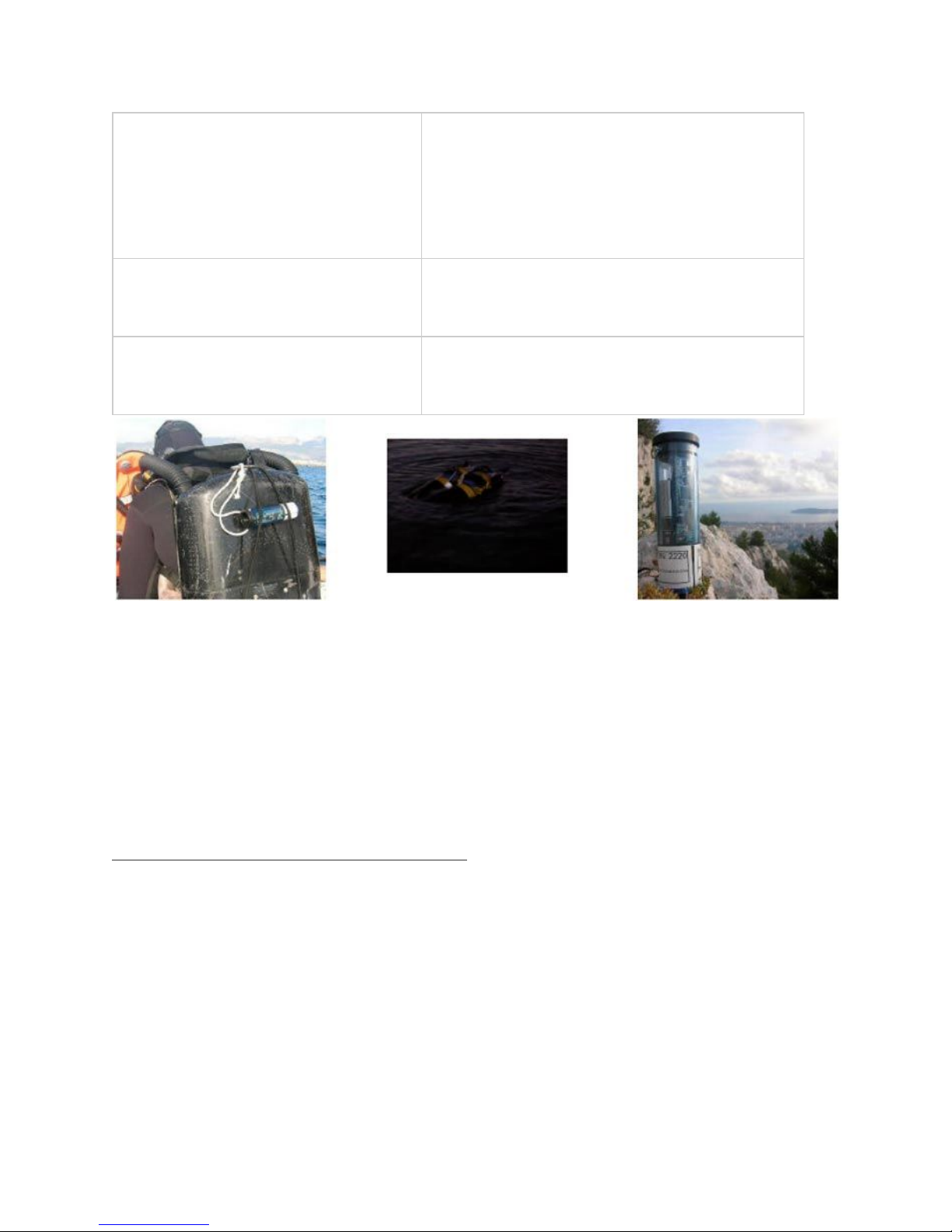
Sonar Transducers
(In the figure at the top: S1, S2, and S3)
Send interrogates to the Transponder and receive
pings from it.
With the data they calculate depth, time of arrival,
and location.
Mobile Station Transponder (TLT-1,
VLT-1 or DS-3)
Attached to target, replies with pings as it receives
interrogates.
DiveBase Software
Collects all data and plots the position of the
target on a grid.
1. Introduction
PILOT™ is a Short Baseline acoustic tracking system. Its principal function is to track a ROV or
other underwater vehicle. PILOT™ uses high frequency (34 kHz - 42 kHz) sound to track the ROV.
While light and most radio waves are quickly absorbed in water, sound actually propagates not only
significantly faster but also much further in water than it does in air. For this reason, sound is used in
many underwater applications. Common examples include depth sounders, imaging sonars and fish
finders.
Principal Components Of The PilotTM System
●The Surface Station is the centerpiece of the PILOT system. Three cabled sonar
transducers (antennae for sound) are connected to the surface station and lowered over
the side of the boat. The transducers form a triangle, which is used to locate the ROV. A
Windows XP computer serves as the data display and entry unit. The Windows computer
runs DiveBase, the surface station software. The ROV range, direction and depth appear
on the screen of DiveBase
●The surface station, and STM-1 or STM-10 will track any underwater vehicle that is
equipped with a ROV Transponder. Several transponders are currently available. The
miniature TLT transponders are designed for tracking small ROV to depths of 330 meters
(1000 feet). The larger and more sophisticated VLT-1 transponder will track ROV to

depths of 1000 meters (3000 feet). It is suitable for mid-size ROV. The surface station is
connected to a Microsoft Windows PC running the DiveBase software.
Figure 1.1 shows how PILOT works. The surface station is on the boat. The three cabled sonar
transducers (acoustic antennas) are lowered over the side. The ROV transponder is mounted on the
underwater vehicle.
Figure 1.1: Target Position Determined By ‘Short Baseline’ Method
To find the ROV position, the surface station will transmit an interrogate signal (two pings) through
transducer #1. This signal travels through the water and eventually reaches the ROV mounted
transponder, which replies with a message that includes its current depth. The reply travels back to
all three surface station transducers. The surface station now measures the time elapsed between
the transmission of the interrogate and the reception of the ROV reply at transducers #1, #2 and #3.
Because the speed of sound in water is fairly well known, these signal run times are easily converted
into distances (d1, d2, d3). Finally, a little trigonometry yields the position of the ROV.
This method of tracking is commonly known as short baseline tracking. The word ‘baseline’ refers to
the imaginary lines that connect the sonar transducers at the surface. The baseline is the reference
for navigation. It is helpful to remember a few characteristics of short baseline tracking.
Characteristics PILOT 'Short Baseline' Tracking
●PILOT shows the position of the target (ROV) relative to the position of the boat or more
specifically relative to the location of the three surface station sonar transducers. If the
boat rotates, the target will appear to move in a circle around the tracking screen.
●PILOT measures the distance of the target with a repeatability of about 0.15 meters,
independent of how far the transducers are spaced apart.

●The accuracy of the direction of the target depends on how far the three surface station
sonar transducers are spaced apart. If they are 3 meters apart, the accuracy is about +/-
5 degrees. If they are 30 meters apart, direction accuracy is about +/- 0.5 degrees
For best accuracy, concentrate target operations broadside to the longer of the two baselines that
are formed by surface transducers #1 and #2, and #1 and #3 respectively.
PILOT Performance Characteristics and Limitations
Short baseline tracking is very convenient. Once the system is set-up, just 'flip the power switch' to
start tracking. The PILOT™ Short Baseline (SBL) technology also lets you choose the accuracy of
tracking by spacing the surface station transducers further apart. When operating from a larger
vessel or the shore, you can often obtain survey (sub-meter) accuracy. In addition, tracking is
available with PILOT even if the target is some distance away but just a fraction of a meter below the
surface.
Yet, despite these capabilities and our customer’s use of PILOT for precision tasks such as
surveying pipelines or serving as a ‘gold standard’ against which other navigation systems are
compared against, the SBL technology does have limits:
The further you move away from the location of your surface station transducers, the further the
tracking accuracy (expressed in meters) will decline. In addition, if you are using GPS and heading
sensor integration in order to operate in a geo-referenced (lat/lon or UTM) frame of work, the error
inherent in those sensors will add to the overall positioning error.
Therefore, requirements that call for consistent sub-meter accuracy over a large area of the sea floor
remain the domain of long baseline (LBL) systems such as Desert Star’s AquaMap system. Due to
our system modularity, your PILOT system is readily upgradeable for precision LBL AquaMap™
work. Check on our web site or call for details.
Geo Referenced Tracking Operations
The main part of this manual describes the basic system operation, which yields target positions
relative to the location of your surface transducers or vessel. Refer to the Appendix for a description
of georeferenced operations and other advanced functions such as chart integration, image
annotations and real-time data export to surveyor’s software such as Hypack™.
2. List of Operational Tasks
The five sections of the installation and operation process contain the following steps. Installing
1. Charge the batteries if necessary
2. Install software
3. Mount the mobile station

4. Conduct initial noise test to determine system noise
Preparing
1. Charge the batteries
Deploying
1. Deploy surface transducers
2. Enter baseline positions in software
3. Check and enter visibility
4. Activate and deploy the mobile station
5. Conduct a noise test to determine ambient (underwater) noise
Operation
1. Start operation
2. Adjust the display
3. Record annotations
4. Retrieve the system
Reporting
1. Replay the survey record
2. Save images of the survey record
3. Create the report document
4. Make the survey record portable
Pilot™ System Components
The specific components included with the Pilot™ system will vary depending upon your
configuration.
Typical components include:
1. 1 Mobile Station (A TLT, VLT, or DS mobile station)
2. An STM surface station
3. Three surface station sonar transducers on 15m or 30m cables
4. Software: DiveBase and Chart Registration
5. This manual and the hardware manuals (for all stations)
Not Included (you must provide):
1. A computer running Windows XP with a minimum of 256MB of RAM.
2. Additional mounting hardware
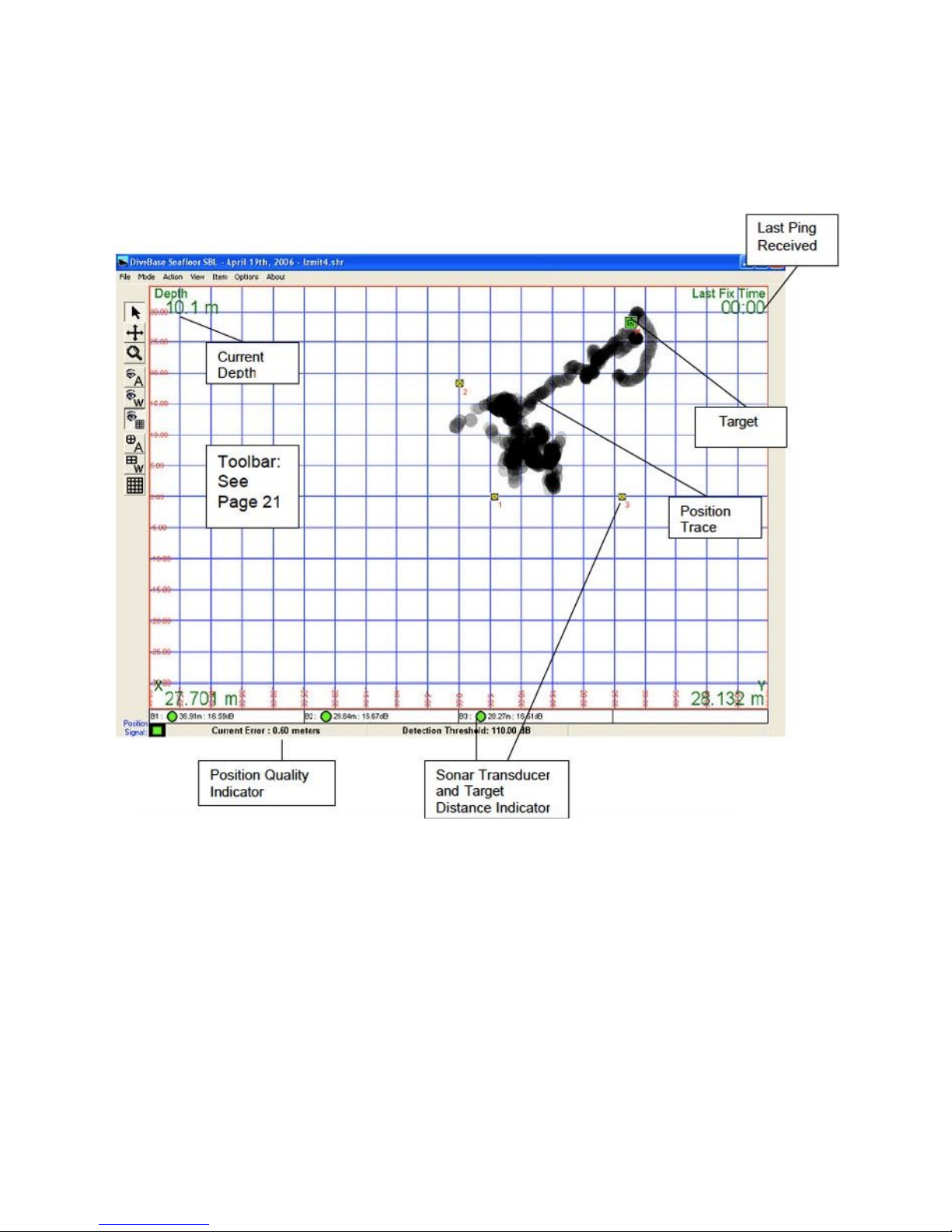
The DiveBase Display
3. Installing the System
These tasks should be done when you first receive the Pilot™ system. The first operation should be
at an inactive test vessel in a quiet location – allow a day to install and learn how to use it.
Installation Tasks
1. Charge the batteries
2. Prepare the stations
3. Install software
4. Mount the Mobile station

5. Connect the surface station to a PC and connect the surface station sonar transducer
cables
6. Test the noise levels
Charge Station Batteries
The STM-10, and VLT series transponders are equipped with rechargeable batteries. The TLT
series transponders use replaceable alkaline batteries. The STM-1 is not equipped with a battery.
Plug each station into the wall with the provided charging units, and turn them on (they will not
charge unless they are on). The red LED light on the end of each station equipped with batteries
should settle into a blink pattern of one second on and one second off. When it is done charging the
pattern will change to one second on and three seconds off.
If the batteries were completely dead they should require about 3.5 hours to finish charging (7 hours
for STM-10). If any other LED blink patterns occur please see the hardware manual (for the VLT-1)
for the table of blink patterns that will tell you what it means.
Always try to charge the batteries a day or two before a mission. The nickel cadmium batteries in the
baseline stations slowly discharge themselves over a period of 6 months, even if they’re not being
used. The batteries provide about 20 hours of continuous use with standard power.
Prepare the Hardware
The stations should be operational after you have charged them. These are the tasks to complete
before they’re ready to put in the water.
1. Check blink patterns: Check that each station turns on and settles into the appropriate
blink pattern of a single short blink once per second. If any other blink pattern occurs
please see the blink pattern table below and/or the hardware manual for the RBS-1
transponder to troubleshoot it.
2. Check dummy plugs: Check to make sure that a dummy plug is plugged into each
exposed waterproof connector on the stations. VLT series transponders require a dummy
plug if the external connector is not being used during in water operations.
3. Mount the mobile station on the ROV, diver or other target.
Blink Pattern
Station Status
One short blink per
second
Ready to go, standby

Triple blink once per
second
Hardware error
Double-blink
Station received a valid interrogate (mobile station) or reply
(surface station)
One sec on, 1 sec off
Charge
One sec on, 3 sec off
Charge done
Rapid blink
Low battery
No blink
Station off or battery dead
Table 3.1: Blink Pattern Meanings
Installing the Software
The software should install itself when you insert the CD into the computer, if it doesn’t do this you
can click on the setup.exe file in the CD directory to initiate the auto-install program.
Mounting the Mobile Station
Figure 3.2: Pony bottle bracket mount

The station must be placed properly. Keep the transducer away from ROV thrusters or other sources
of noise. Ideally the transducer should be “free and clear”, i.e. the near space around it should not
have anything in it that will obstruct or reflect the sound waves used by the system.
For a diver: A VLT or TLT can be mounted on the SCUBA tank using a pony bottle bracket. If the
diver uses a DS-1, it can just be attached to his BC.
For an ROV: hose clamps can be used to mount a VLT or TLT, or possibly Velcro to mount a DS-1.
Connect the Surface Station
Figure 3.3: Velcro mounted DS-1
Connect the STM to an available PC RS-232 port. If you are using a computer without a legacy
RS-232 port, a USB adapter will be required.
Insure that the proper COM port has been selected in the DiveBase™ application. The COM port
can be changed through the Options/Mobile Station Com Ports
option on the menu bar.
Connect the three cabled surface station sonar transducers to the STM-1 or STM-10 surface station.
Test the System Noise Levels
Shipboard hardware, ROV and most other systems emit noise and must be tested to be sure the
noise is within acceptable levels for system operation.
Table of contents
Popular Marine Equipment manuals by other brands




Clarion
Clarion GR10BT Owner's manual & installation manual

Raymarine
Raymarine Maxiview ST80 Owner's handbook

GUIDANCE MARINE
GUIDANCE MARINE 20- Series Installer's guide

Raymarine
Raymarine ST60 Tridata Owner's handbook

olympia electronics
olympia electronics ΒS-531/1/MAR quick start guide

Sonic
Sonic 2024 Operation manual