
Denville Scientific M3100 Series User manual

1
M3100 SERIES
MICROSCOPE
OPERATION MANUAL
Denville Scientific, Inc.
P.O. Box 4588, Metuchen, NJ 08840-4588; USA
www.denvillescientific.com
Tel: 800-453-0385/ 908-757-7577 Fax: 908-757-7551
Contents
Safety, General Information ……………….…………………………………………………………………..……… 3

2
1. Before Use …………………………………………………………………………………………………………. 4
1.1 Notice …………………………………………………………………………………………………………… 4
1.2 Maintenance ………………………………………………………………………………………………… 5
1.3 Power Requirement and Fuse ………………………………………………………………………. 5
2. Unpack and Assemble the Microscope ………………………………………………………………. 6
2.1 Unpacking ……………………………………………………………………………………………………. 6
2.2 Assembly ……………………………………………………………………………………………………… 6
3. Operation …………………………………………………………………………………………………………. 7
3.A Install and Set the Condenser …………………………………………………………………….. 7
3.1 Illumination and Adjustments …………………………………………………………………….. 8
3.2 Slide Holder ………………………………………………………………………………………………… 9
3.3 Focusing and Diopter Adjustment ………………………………………………………………. 9
3.4 Focusing Tension Adjustment …………………………………………………………………….. 10
3.5 Interpupillary Distance Adjustment ……………………………………………………………. 10
3.6 Centering the Condenser ……………………………………………………………………………. 11
3.7 The Field Diaphragm (Koehler) Setting ………………………………………………………. 12
3.8 The Condenser Iris Diaphragm Setting ………………………….…………………………… 12
3.9 Use 100X Oil Immersion Objective …………………………………………………………….. 13
3.10 Correct Filter Use …………………………………………………………………………………….. 14
3.11 Using the Trinocular Head for Video/Photography …………………….………….. 14
4. Replacing the Fuse …………………………………………………………………………………………… 15
5. Replacing the LED Assembly ……………………………………………………………………………. 16
6. General Specifications ………………………………………………………………………………………. 16
7. Trouble Shooting ………………………………………………………………………………………………. 18
8. M3100 Microscope Diagram ……………………………………………………………………………….. 21
DENVILLE SCIENTIFIC M3100 Series Microscope

3
We thank you for choosing the Denville Scientific M3100 Series Microscope. This precisely built, durable microscope
should give you years of service to even the busiest office practice. Our technical and customer support departments
stand ready to assist you with any questions or comments you may have. Please read this manual carefully before you
operate the microscope.
Warning: The microscope must be used in a manner as specified in this manual or the overall safety may be impaired.
If ever you require an additional accessory or spare part, please contact your local distributor, or you can contact
DENVILLE SCIENTIFIC for the name of the nearest distributor.
Safety, General Information
The microscope described in this manual is designed to be used by properly trained personnel in a suitably equipped
laboratory. For the correct and safe use of this microscope it is essential that laboratory personnel follow generally
accepted safe procedures in addition to the safety precautions called for in this manual.
The inside of the illumination base is a hazardous area and the cover should not be removed. ANY Servicing must be
done by an authorized technician.
Please carefully read the Safety, Electrical, Warning, Performance instructions below.
Safety
This microscope has been designed and tested in accordance with EN 61010 Safety Requirements for Electrical
Equipment for Measurement, Control, and Laboratory Use. This microscope has been supplied in a safe condition.
Read the following before installing and using the instrument and its accessories.
Electrical
Before switching on the microscope, make sure it is set to the voltage of the local power supply (see Installation). The
M3100 Series features a broad range power system, 90 –240 Volts.
The main plug shall be inserted in a socket provided with a protective earth (grounded) contact. The protective action
must not be negated by the use of an extension cord without a protective conductor.
Warning
Any interruption of the protective conductor inside or outside the microscope or disconnection of the protective earth
terminal is likely to make the microscope dangerous. Intentional interruption is prohibited. Whenever it is likely that
the protection has been impaired, the microscope shall be made inoperative and be secured against any unintended
operation.
The protection is likely to be impaired if, for example, the apparatus or power cord

4
Shows visible damage
Fails to perform the intended measurements
Has been subjected to prolonged storage under unfavorable conditions
Has been subjected to rough or severe transport
Safety Signs and Symbols
Proper labels and symbols are used to supply important information for safety and performance. The operating
personnel must fully understand the meanings of those labels and symbols before operating the microscope.
Read the manual before using. Faulty operation could lead to injury or instrument malfunction.
|
Power switch ON
O
Power switch OFF
The optimum environment: Temperature 5 –35 ℃
Humidity 80 %
1. Before Use
1.1 Notice
1.1.1 As the microscope is a precision instrument, always operate it with care, on a clean and dry, non-vibrating surface.
1.1.2 Do not operate in direct sunlight, or in the high temperature, damp, or dusty environments.
1.1.3 When moving the microscope always use both hands to hold ①and ②as shown in Figure 1, and set it down
with care. ★If holding the focusing knob, eyepiece tube or stage during moving, you may cause damage.
1.1.4 During operation, the field condenser ③may become warm/hot. Please make sure enough space around the
field condenser for cooling ( Figure 2).
1.1.5 Connect the microscope to power supply outlet with proper earthed ground to avoid electric shock.
1.1.6 The M3100 microscope has LED illumination system and bulb replacement is not necessary. In case the LED does
need to be replaced, make sure the power switch ④is set at“0”(off) and disconnect the power cord and wait until
the LED cools down before replacing the LED or the LED illuminator.

5
1.1.7 The power input voltage is 90~240V. Make sure the voltage supply is within this range.
Figure 1
Figure 2
Figure 3
1.2Maintenance
1.2.1 Wipe the lenses gently with a soft lens tissue. Carefully wipe off oil or finger prints on the lens surfaces with lens
paper or tissue. If the oil is dried on objective lenses it may be difficult to remove. Please use tissue moistened an optical
cleaning solution designed for “Coated” optics. Beginning in the center of the lens or eyepiece, rub the lens in an ever-
widening circle, until you reach the outer edge of the lens, or eyepiece surface. This is the best way to remove dust, dirt,
or oil and move it off to the side, or onto the moistened lens tissue.
1.2.2 Do not use an organic solution/solvent to attempt to clean the surfaces or other microscope components.
1.2.3 In the event liquid is spilled on the microscope damped by liquid, unplug the instrument immediately and wipe it
dry, then allow at least 24 hours for the unit to dry thoroughly before plugging it in again.
1.2.4 If you must disassemble the microscope yourself, unplug it first and exercise caution.
1.2.5 When the microscope is not in use, please cover the microscope with a dust cover.
1.3. Electronics and Fuse
Your Denville Scientific M3100 microscope uses U/L and CSA approved electrical components. There are no user
repairable parts in the illumination base. Any service here must be done by authorized Denville Scientific service
personnel.
Input: AC 90-240V/50-60Hz.
Output: 4.5V for LED
Warning: In order to avoid potential electrical hazard, replace only with the same type and rated LED.

6
Fuse: 250V 1A fuse is used to protect the illuminator from electrical overload. The two fuse cases are located near the
power inlet one the back of the microscope. When replacing the fuse, always unplug the instrument first then install a
new one of the same size and amperage.
Warning: In order to avoid electrical hazard, replace only with the same type and rated fuse.
2. Unpack and Assemble the Microscope
2.1 Unpacking your Denville Scientific M3100 Series Microscope
Each Denville Scientific microscope has been packed with utmost care. Please take a moment to examine the outer and
inner cartons for any visual damage. We recommend that you keep all of the packing material until you have fully
assembled, examined and tested your new microscope. If you note any damage, please contact the shipping company or
your distributor immediately as there are time limits on making freight damage claims.
Unpack your M3100 microscope using the following checklist for the parts and accessories. (Model M3127 is used as an
example. Your specific order may vary)
1M3100 Microscope stand
1 Condenser
1 Binocular head
2 10x eyepieces
4 Achromatic objectives 4x, 10x, 40xr and 100xr (oil)
2 Replacement fuses (250V 1A slow blow)
1 Each Blue filter; Dust cover and Operation Manual
If any parts are missing, please call Denville Scientific customer service at 800-453-0385 or e-mail us at
info@DenvilleScientificsci.com. Please be ready with the serial #, date of purchase and name of supplier.
2. 2 Assembly of your new M3100 Series microscope
Remove the microscope from the packing and place it on a sturdy, clean and dry surface. Do not touch optics or lenses
with your bare hands. The following illustrated figure will help you get familiar with the components that are required to
be installed on site.

7
Fig. 4 M3100 and Components
1. Condenser
2. Objective
3. Illuminator
4. Eyepiece
5. Power cord
2.2.1 Install and Set the Condenser
1.) Turn the coarse focus knob (① in Figure 5) to raise the stage to its highest position.
2) Turn the condenser holder knob (②in Figure 5) to lower the condenser holder to its lowest position.
3) Loosen the condenser locking screw on the holder (③in Figure 5). Slide the condenser into the holder. The guiding
screw on the back side should go into the slot of the condenser holder.
4) Tighten the locking screw ③to secure the condenser in place. Use the condenser holder knob ②to move the
condenser up to the highest position.

8
Fig. 5 Install Condenser
2.2.2 Install the Objectives (some models come with Objectives pre-installed)
1) Turn the coarse knob (① in Figure 6) to lower the stage for easy access to the nosepiece.
2) Install the objectives (②in Figure 6) from lower power (magnification) to higher power clockwise.
★Note: Lower power objective (such as 4X or 10X) is usually used first to locate the image.
★Note: The nosepiece will make a click to indicate an objective is properly positioned.
Fig.6 Install Objectives
2.2.3 Install Eyepieces

9
Remove the plastic caps from the eyepiece tube holes. Please make sure to keep dust and dirt from getting into the
eyepiece tubes. Store caps in a proper place. Slide the eyepieces into place in the eyepiece tubes.
Plug in the power cord into the power inlet at the back of the microscope to finish the assembly.
3. Operation
3.1 Illumination and Adjustment
Set the power switch ①at “ON”; and use the illumination rheostat knob ②to adjust the brightness.
Fig. 7 Illumination and Adjustment
3.2 Slide Holder
Put a slide ②on the mechanical stage and hold the slide with the slide holder. Make sure the cover glass is on
top of the slide. Using the mechanical stage controls ③, center the specimen on the slide under an objective.
Fig. 8 Slide Holder
3.3 Focusing and Diopter Adjustment
10
3.3.1 Set the 4X objective into light path. Turn the nosepiece to switch objectives. Use the coarse adjust to bring 4X into
focus. You may choose to rotate the nosepiece clockwise to bring the 10X into the light path.
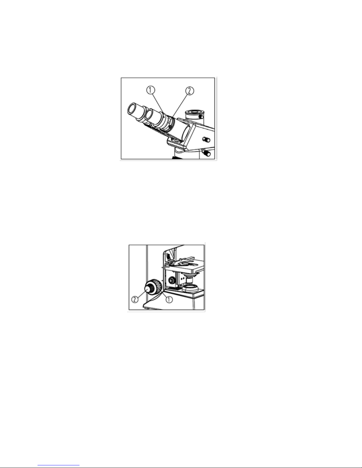
3.3.2 Rotate the diopter rings ①(Fig.9) on both the left and right eyepiece tubes so that the “0” on the diopter ring is
set at the center line mark ②on the eyepiece tubes.
Fig. 9 Diopter and Setting
3.3.3 Using your right eye to view the slide; using the focus controls on the microscope turn the coarse focusing knob ①
(Fig.10) and then the fine focusing knob ②to bring the slide specimen into sharp focus through that eyepiece.
Fig.10 Coarse and Fine Focusing
3.3.4 Next, view the slide with the left eyepiece. Adjust the left diopter until the image is sharp, clear and in focus (do
not use the coarse and fine focus controls). You should now be in sharp focus with both your right and left eyes.
★Diopter adjustment range is ±5.
★You may want to remember your own diopter setting for future use.
Table of contents
Other Denville Scientific Microscope manuals


Popular Microscope manuals by other brands


VWR
VWR VisiScope 384 Series instruction manual
Nikon
Nikon ECLIPSE E200 POL instructions

Leica
Leica DI C800 User's manual & installation instructions

ThermoFisher Scientific
ThermoFisher Scientific Continuµm manual

ThermoFisher Scientific
ThermoFisher Scientific Continuµm manual

Olympus
Olympus SZ61 instructions