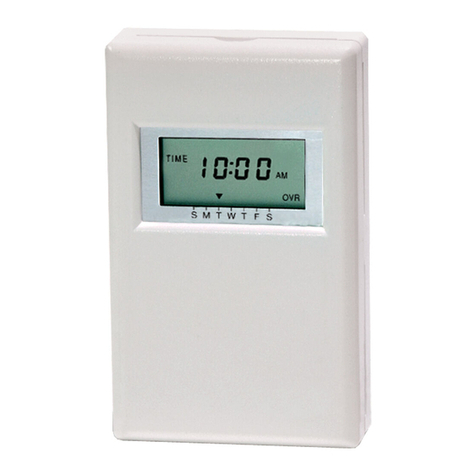
Denlar ClockBox Pro User manual

Clock Box PRO Installation and Operations Manual V1.1

Clock Box PRO Installation and Operations Manual V1.1 LAB-110218
2
TABLE OF CONTENTS
Installation
1. Clock Box PRO and Hood Interface Diagram Non-Plug‘N’Play 4-5
2. Clock Box PRO and Hood Interface Diagram Plug‘N’Play 6-7
3. Plug‘N’Play Layout 8-9
4. Device Flow Chart 10
5. Clock Box Stand-Alone Interface Diagram Non-Plug‘N’Play 11-12
6. Clock Box PRO Stand-Alone Interface Diagram Plug‘N’Play 13-14
7. Device Flow Chart Clock Box PRO Only 15
8. Touch Screen Mounting 16-17
9. ENT Flexible Conduit Installation 18
Operation and Setups
10. Operating the Clock Box PRO 19
11. Timer Setup 20
12. Password Setup and Reset 21-22
13. Handicap Accessible Controls (ADA) 23
14. Language Setup 24
Status Screens
15. Main Screen Faults 25
16. Status Screen 26
Option Screens
17. Bypass Setup 27
18. Monitoring System 28-30
19. No Hood Connected 31
Technical Data
20. Troubleshooting Quick Guide 32
21. Clock Box PRO Schematic 33
22. Clock Box PRO Datasheet 34
23. Gas Disconnect Datasheet 35
24. Electrical Disconnect Datasheet 36
25. Contact Information 37

Clock Box PRO Installation and Operations Manual V1.1 LAB-110218
3
READ AND SAVE THESE INSTRUCTIONS
WARNING
TO REDUCE THE RISK OF FIRE, ELECTRIC SHOCK, OR INJURY TO PERSON, OBSERVE THE FOLLOWING:
1. Use this unit only in the manner intended by the manufacturer. If you have questions, contact the manufacturer at the
address or telephone number listed on the front cover of this manual.
2. Before servicing or cleaning unit, switch power OFF at service panel and lock the service disconnecting means to
prevent power from being switched on accidentally. When the service disconnecting means cannot be locked, securely
fasten a lockout / tagout device based on local codes.
3. Installation work and electrical wiring must be done by a qualified person in accordance with all applicable codes and
standards, including fire-rated construction codes and standards.
4. When cutting or drilling into wall or ceiling, do not damage electrical wiring and other hidden utilities.
5. To reduce the risk of fire or electric shock, do no use this device other than specified by the manufacturer.
6. Utilize approved wiring only.
7. This unit must be grounded.
DISCLAIMER: DENLAR Fire Protection shall not be liable for errors
contained in this manual or for incidental, consequential damages in
connection with the furnishing, performance or use of this information.
DENLAR Fire Protection makes no warranty of any kind with regards to
this information, including, but not limited to the implied warranties of
merchantability and fitness for a particular purpose.
G

Clock Box PRO Installation and Operations Manual V1.1 LAB-110218
4
Clock Box PRO and Hood Interface Diagram
Non-Plug‘N’Play
1. 120 VAC Input (not provided)
a. 120 VAC / 15 Amp circuit (provided by installer)
2. Junction Box (not provided)
a. Run the 120 VAC Input to the Junction Box
b. Run the 12-2 MC (3) wire, with the red tape, from the Hood to the Junction Box
c. Run a new cable (4) (not provided) from the Junction Box to the Clock Box PRO Control
Box
d. Wire nut the Hot leads from the three wires (1, 3, 4) together
e. Wire nut the Neutral leads from the three wires (1, 3, 4) together
f. Connect the grounds accordingly (1, 3, 4)
3. Metal Clad 12-2 MC wire with red tape from the Hood (provided)
4. Cable to provide 120 VAC from the Main Breaker Panel to the Clock Box PRO (not provided)
1
3
120 VAC Input (not provided)
6
5
4
7
8
10
9
Electrical Disconnect
CB1 / CB2
2
ED1

Clock Box PRO Installation and Operations Manual V1.1 LAB-110218
5
a. Connect the Line side to position four of the eight (8) position Power Plug in the Clock Box
PRO Control Box
b.
Clock Box PRO and Hood Interface Diagram
Non-Plug‘N’Play
c. The Neutral wire connects to the neutral of the 14/2 MC wire (5). A jumper is also
connected to the two Neutrals and inserted into position two of the eight (8) position
Power Plug in the Clock Box PRO Control Box
d. Connect the Ground to the ground bar
5. Metal Clad 14-2 MC wire with black tape from the Hood (provided)
a. Connect the 14-2 MC wire with black tape to the eight (8) position Power Plug in the Clock
Box PRO Control Box
1. The Line side connects to position one of the eight (8) position Power Plug in the Clock
Box PRO Control Box
2. Connect the Neutral according to 4-b listed above
3. The Ground connects to position three of the eight (8) position Power Plug in the
Clock Box PRO Control Box
6. 24VDC and 120VAC Hood interface cable (provided)
7. 24 VDC Input / Output Communication cable encased in 16 mm ENT Flexible Conduit (provided)
a. 25 Ft in length
b. One communication (Ethernet) cable and one plenum cable
c. Connects between the Clock Box PLC and HMI / Touch Screen
8. Output Power Disconnect Cable (provided)
a. Connect the other end to the coil of the Power Source Disconnect (D1000-E, D1000-G, or
D1000-DED)
9. Jumper cable for the D1000-DED if applicable (not provided)
10. Supply Line 120-220 VAC from the Main Breaker Panel to the D1000-E (not provided)
Empty
Ground
Neutral
Line
120 VAC from Main Breaker
Panel
Ground
Neutral
Line
Clock Box PRO Control Box Power Plug
Clock Box Side
Installer Side

Clock Box PRO Installation and Operations Manual V1.1 LAB-110218
6
Clock Box PRO and Hood Interface Diagram
Plug‘N’Play
1. 120 VAC Input (not provided)
a. 120 VAC 15 Amp circuit provided by installer
b. Voltage supply from the Main Breaker Panel to the 5-15R Receptacle (not provided)
2. 120 VAC 15 Amp Plug Input to Hood (provided)
a. 6 Ft in length
b. Power Cord from the Hood and connects to the 5-15R Receptacle (not provided)
3. 120 VAC Output from Hood encased in 16 mm ENT Flexible Conduit (provided)
a. 10 Ft in length
b. One plenum cable
c. Cable from the Hood to the Power Source Disconnect for the Range (Gas or Electric)
d. One four-position connector
i. Labeled HD1
7
120 VAC Input (not provided)
10
Electrical Disconnect
GD2
JP1, ED2, GD4
Jumper for D1000-DED
5
9
3
1
2
6
4
CB1 / CB2
ED1
Gas Disconnect
GD1

Clock Box PRO Installation and Operations Manual V1.1 LAB-110218
7
1. Four Wires
4. 120 VAC Input/Output to/from the Clock Box encased in 16 mm ENT Flexible Conduit (provided)
a. 10 Ft in length
b. Two plenum cables
c. Cable from the Clock Box to the Power Source Disconnect for the Range (Gas or Electric)
d. Two four-position connectors
i. Labeled CB1
1. Four wires
ii. Labeled CB2
1. Three wires
e. One eight-position connector
i. Labeled CB3
1. Seven wires
5. 120 VAC Input to Gas Disconnect (DED option) encased in 16 mm ENT Flexible Conduit (provided)
a. 10 Ft in length
b. One plenum cable
c. Cable from the Gas Disconnect junction box to the Electrical Disconnect
d. Two four-position connectors
i. Labeled GD2
1. Located at the Gas Disconnect junction box
ii. Labeled GD3
1. Located at the Electrical Disconnect
6. 24 VDC Input / Output Communication cable encased in 16 mm ENT Flexible Conduit (provided)
a. 25 Ft in length
b. One communication (Ethernet) cable and one plenum cable
c. Connects to the Clock Box PLC and HMI / Touch Screen
7. Power Source Disconnect
a. One four-position connector
i. Label depends on the Power Source Disconnect option
1. D1000-E-120/220 (Electrical)
a. Labeled ED1
2. D1000-G (Gas)
a. Labeled GD1
3. D1000-DRD
a. Labeled ED1
4. D1000-DED
i. D1000-E-120/220 Labeled ED1
ii. D1000-G Labeled GD1
iii. Jumper Wire JP1, ED2,GD2
8. Connecting the four-position connectors from the Hood, the Clock Box, and the Power Source
Disconnect.
9. 120-220 VAC supply line to Range via Electric Disconnect (not provided)
10. 24VDC and 120VAC Hood interface cable (provided)

Clock Box PRO Installation and Operations Manual V1.1 LAB-110218
8
Plug‘N’Play Layout
D1000, D1000-G, and Clock Box PRO

Clock Box PRO Installation and Operations Manual V1.1 LAB-110218
9
Plug‘N’Play Layout
D1000, D1000-E, and Clock Box PRO
D1000, D1000-DED, and Clock Box PRO

Clock Box PRO Installation and Operations Manual V1.1 LAB-110218
10
Device Flow Chart
Table of contents