Deluo TRISTAR25 User manual

1
TRISTAR25 GPS Receiver Module
User’s Guide

Deluo Electronics http://www.deluo.com
2
Manual Revision History
Revision Date Update Summary
Issue A December 2002 Initial release
Issue B February 2003 Add pins electrical characteristics

Deluo Electronics http://www.deluo.com
3
1 INTRODUCTION ............................................................................................... 5
1.1 OVERVIEW............................................................................................................. 5
1.2 FEATURES .............................................................................................................. 5
2 RECEIVER OPERATION............................................................................... 6
3 HARDWARE INTERFACE............................................................................. 7
3.1 RF CONNECTOR .................................................................................................... 7
3.2 INTERFACE CONNECTOR........................................................................................ 7
3.3 MECHANICAL DIMENSIONS AND INTERFACE CONNECTOR..................................... 8
3.4 INTERFACE CONNECTOR PIN OUT.......................................................................... 9
3.4.1 Molex Connector JP3........................................................................................ 9
3.4.2 Pin Header Connector JP2.............................................................................. 10
3.5 ONE-PULSE-PER-SECOND OUTPUT.......................................................................11
3.6 RTCM DIFFERENTIAL DATA................................................................................11
4 SOFTWARE INTERFACE............................................................................ 12
4.1 NMEA OUTPUT MESSAGE SPECIFICATION.............................................. 12
4.1.1 NMEA Checksum Calculation.......................................................................... 12
4.1.2 GGA – Global Positioning System Fix Data...................................................... 13
4.1.3 GLL – Geographic Position – Latitude / Longitude ........................................... 14
4.1.4 GSA – GNSS DOP and Active Satellites............................................................ 15
4.1.5 GSV – GNSS Satellites in View......................................................................... 16
4.1.6 RMC – Recommended Minimum Specific GNSS Data........................................ 17
4.1.7 VTG – Course Over Ground and Ground Speed................................................ 18
4.2 EVERMORE BINARY MESSAGE SPECIFICATION .................................... 19
4.2.1 Binary Input Messages.................................................................................... 21
4.2.1.1 EverMore Binary Input Message 0x80: Initialization .......................................... 21
4.2.1.2 EverMore Binary Input Message 0x81: Data Logging......................................... 22
4.2.1.3 EverMore Binary Input Message 0x86: Set Elevation Mask................................. 22
4.2.1.4 EverMore Binary Input Message 0x87: Set DOP Mask ....................................... 22
4.2.1.5 EverMore Binary Input Message 0x8F: Set Operating Mode................................ 23
4.2.1.6 EverMore Binary Input Message 0x94: Differential GPS Control.......................... 24

Deluo Electronics http://www.deluo.com
4
4.2.2 Binary Output Messages.................................................................................. 25
4.2.2.1 EverMore Binary Output Message 0x02: Navigation Data................................... 25
4.2.2.2 EverMore Binary Output Message 0x04: DOP Data ........................................... 26
4.2.2.3 EverMore Binary Output Message 0x06: Channel Status..................................... 27
4.2.2.4 EverMore Binary Output Message 0x08: Measurement Data................................ 28
4.3 DATA LOGGING.................................................................................................... 29
4.3.1 Data Logging Input Messages.......................................................................... 29
4.3.1.1 LogConfig Set............................................................................................. 29
4.3.1.2 LogData Dump ........................................................................................... 30
4.3.1.3 LogData Erase ............................................................................................ 30
4.3.1.4 LogConfig Read.......................................................................................... 30
4.3.2 Data Logging Output Messages ....................................................................... 31
4.3.2.1 LogData..................................................................................................... 31
4.3.2.2 LogConfig Info ........................................................................................... 31
4.3.3 Data Logging Programming Description.......................................................... 32
4.3.3.1 Configuring for Data Logging........................................................................ 32
4.3.3.2 Retrieving Logged Data................................................................................ 32
APPENDIX A SUPPORTED DATUM LIST........................................ 33
APPENDIX B DEFAULT VALUES.......................................................... 40

Deluo Electronics http://www.deluo.com
5
1 Introduction
1.1 Overview
The TISTAR25 GPS Receiver is intended for use in a wide range of applications. The receiver
simultaneously tracks up to twelve satellites, provides accurate satellite positioning data with
fast time-to-first-fix (TTFF) and low power consumption. It is designed for high performance
and maximum flexibility in a wide range of applications including mobile asset tracking,
in-vehicle automotive guidance, location sensing, telematics and so on. The highly integrated
receiver achieves high performance, minimizes board size and power consumption
requirements. The TISTAR25 is designed to withstand harsh operating environments; however,
it should be used inside an enclosure as a part of the application product designed by the
system integrator.
1.2 Features
The TISTAR25 GPS receiver offers following features:
! Twelve parallel tracking channels
! Fast TTFF and low power consumption
! Compact design suitable for applications requiring small space
! Differential correction using real-time RTCM SC-104 data
! On-board rechargeable battery sustained real-time clock and memory for fast satellite
reacquisition during power-up
! High accuracy one-pulse-per-second output
! Upgradeable firmware using flash-based program memory
! Supports NMEA-0183 protocol
! Full navigation accuracy achievable with Standard Positioning Service
! Optimized for navigation in urban-canyon environments
! Automatic cold start with no user initialization required

Deluo Electronics http://www.deluo.com
6
2 Receiver Operation
Upon power up, after initial self-test has completed, the TISTAR25 will begin satellite
acquisition and tracking process. Under normal open-sky condition, position-fix can be
achieved within approximately 45 seconds (within 15 seconds if valid ephemeris data is
already collected from recent use). After receiver position has been calculated, valid position,
velocity and time information are transmitted through the on board serial interface.
The receiver uses the latest stored position, satellite data, and current RTC time to achieve
rapid GPS signal acquisition and fast TTFF. If the receiver is transported over a large distance
across the globe, cold-start automatic-locate sequence is invoked. The first position fix may
take up to five minutes searching the sky for the GPS signal. The acquisition performance can
be improved significantly if the host initializes the receiver with a rough estimate of time and
user position.
As soon as GPS signal is acquired and tracked, the TISTAR25 will transmit valid navigation
information through its serial interface. The navigation data contains following information:
! Receiver position in latitude, longitude, and altitude
! Receiver velocity
! Time
! DOP error-magnification factor
! GPS signal tracking status
The TISTAR25 will perform 3D navigation when four or more satellites are tracked. When three
or fewer satellites are tracked, altitude-hold is enabled using the last computed altitude and 2D
navigation mode is entered.
With signal blockage or rising and setting of the satellites, where a change in satellite
constellation used for position fix occurred, large position error may result. The TISTAR25
incorporates a proprietary algorithm to compensate the effect of satellite constellation change,
and maintains an accurate smooth estimate of the receiver’s position, velocity, and heading.

Deluo Electronics http://www.deluo.com
7
3 Hardware Interface
3.1 RF Connector
The RF connector is a 50 ohm straight MCX snap-on coaxial RF jack receptacle.
3.2 Interface Connector
There are three interface connectors, the first is a 10-pin Molex connector, the second is a
16-pin golden finger, and the third is a 16-pin header.

Deluo Electronics http://www.deluo.com
8
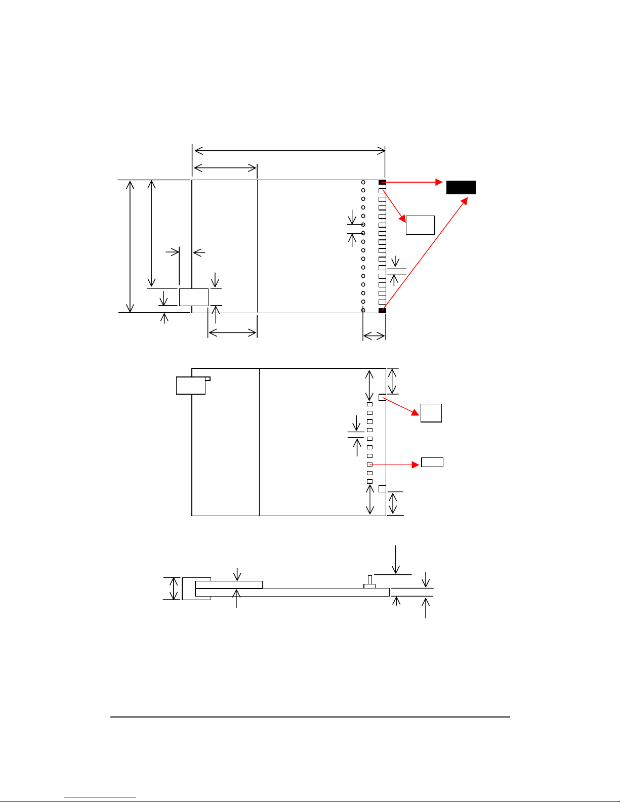
3.3 Mechanical Dimensions and Interface Connector
Unit: mil 1780
734 100
40
100
1225 985 78.74 50
150 RF
28
197
43 459 239
Top View
420 324
84
84
18
62.992
31.496
364 261
Bottom View
290
120 RF Shield 45
200
Lateral View
Figure1

Deluo Electronics http://www.deluo.com
9
3.4 Interface Connector Pin Out
3.4.1 Molex Connector JP3
1
JP3
EverMore
BBP1204
1
10-pin Molex
connector
pin-1
Figure 2
Pin Function Input/Output Level Pin Function Input/Output Level
1 TXD0 Output LVTTL 2 RXD0 Input LVTTL
3 PWR_IN Input 3.3V 4 GND Ground 0V
5 LED0 In/Out LVTTL 6 1PPS Output LVTTL
7 TXD1 Output LVTTL 8 RXD1 Input LVTTL
9 VBAT Input 3.3V 10 ANT PWR Input
The following is a functional description of the pins on the 10-pin interface connector.
Pin 1. TXD0: Serial port output # 1 (GPS navigation output)
Pin 2. RXD0: Serial port input # 1 (command input)
Pin 3. PWR_IN: Power supply input, regulated 3.3V, 112mA
Pin 4. GND: Ground
Pin 5. LED0: Reserved I/O port 31 from CPU
Pin 6. 1PPS: 1-pulse-per-second output. Active high for approx. 1usec
Pin 7. TXD1: Serial port output #2 (currently unused)
Pin 8. RXD1: Serial port input #2 (DGPS input)
Pin 9. VBAT: External backup battery charging input
Pin 10. ANT PWR: External active antenna power input

Deluo Electronics http://www.deluo.com
10
3.4.2 Pin Header Connector JP2
JP2 16-Pin Header
16-PinGoldenFinger
RF SRAM Flash
Antenna Connector Pin1 Pin1
Pin header parallel golden finger
Figure 3
Pin Function Input/Output Level Pin Function Input/Output Level
1 PIO1 In/Out LVTTL 2 PIO10 In/Out LVTTL
3 PIO11 In/Out LVTTL 4 TXD0 Output LVTTL
5 RXD0 Input LVTTL 6 PWR_IN Input 3.3V
7 GND Ground 0V 8 LED0 In/Out LVTTL
9 1PPS Output LVTTL 10 TXD1 Output LVTTL
11 RXD1 Input LVTTL 12 VBAT Input 3.3V
13 ANT PWR Input 14 PIO12 In/Out LVTTL
15 PIO13 In/Out LVTTL 16 PIO14 In/Out LVTTL
The following is a functional description of the pins on the 16-pin interface connector.
Pin 1. PIO1: Reserved I/O port 1 from CPU
Pin 2. PIO10: Reserved I/O port 10 from CPU
Pin 3. PIO11: Reserved I/O port 11 from CPU
Pin 4. TXD0: Serial port output # 1 (GPS navigation output)
Pin 5. RXD0: Serial port input # 1 (command input)
Pin 6. PWR_IN: Power supply input, regulated 3.3V, 112mA
Pin 7. GND: Ground
Pin 8. LED0: Reserved I/O port 31 from CPU
Pin 9. 1PPS: 1-pulse-per-second output. Active high for approx. 1usec
Pin 10. TXD1: Serial port output #2 (currently unused)
Pin 11. RXD1: Serial port input #2 (DGPS input)
Pin 12. VBAT: External backup battery charging input
Pin 13. ANT PWR: External active antenna power input
Pin 14. PIO12: Either Reserved I/O port 12 from CPU or INT5
Pin 15. PIO13: Either Reserved I/O port 13 from CPU or INT6
Pin 16. PIO14: Reserved I/O port 14 from CPU
Table of contents