Deif AGC 150 User manual

OPERATOR'S MANUAL
AGC 150
Generator marine
Stand-alone
4189341314A

1. Introduction
1.1 Symbols for hazard statements......................................................................................................................................................................................... 3
1.2 About the operator's manual...............................................................................................................................................................................................3
1.3 Warnings and safety.................................................................................................................................................................................................................4
1.4 Legal information.......................................................................................................................................................................................................................4
2. About the AGC 150 Stand-alone marine
2.1 Stand-alone (island mode)....................................................................................................................................................................................................5
2.1.1 Display, buttons and LEDs............................................................................................................................................................................................. 5
2.2 Emergency genset.....................................................................................................................................................................................................................6
2.2.1 Display, buttons and LEDs............................................................................................................................................................................................. 7
2.3 Display settings.......................................................................................................................................................................................................................... 8
2.4 Mimic function............................................................................................................................................................................................................................. 8
2.5 Running modes...........................................................................................................................................................................................................................9
3. Menus
3.1 Menu structure..........................................................................................................................................................................................................................10
3.2 Settings menu........................................................................................................................................................................................................................... 10
3.2.1 Menu numbers.................................................................................................................................................................................................................. 11
3.2.2 The jump to parameter function.................................................................................................................................................................................11
3.3 View menu................................................................................................................................................................................................................................... 11
3.3.1 Display views.....................................................................................................................................................................................................................12
3.3.2 Display text.........................................................................................................................................................................................................................13
3.4 Status texts.................................................................................................................................................................................................................................14
3.5 Service view............................................................................................................................................................................................................................... 15
3.6 Engine drive shortcut menu..............................................................................................................................................................................................15
3.7 Exhaust after-treatment (Tier 4/Stage V).................................................................................................................................................................... 16
4. Alarm handling and log list
4.1 Alarm handling......................................................................................................................................................................................................................... 18
4.2 Logs menu.................................................................................................................................................................................................................................. 19
OPERATOR'S MANUAL 4189341314A EN Page 2 of 19

1. Introduction
1.1 Symbols for hazard statements
DANGER!
This shows dangerous situations.
If the guidelines are not followed, these situations will result in death, serious personal injury, and equipment damage or
destruction.
WARNING
This shows potentially dangerous situations.
If the guidelines are not followed, these situations could result in death, serious personal injury, and equipment damage
or destruction.
CAUTION
This shows low level risk situation.
If the guidelines are not followed, these situations could result in minor or moderate injury.
NOTICE
This shows an important notice
Make sure to read this information.
1.2 About the operator's manual
This document gives the necessary information to operate the controller.
CAUTION
Installation errors
Read this document before working with the AGC 150 controller. Failure to do this may result in human injury or damage
to the equipment.
Intended users of the operator's manual
The operator's manual is for the operator that uses the controller regularly.
The manual describes the LEDs, buttons and screens on the controller, alarm handling, and the logs menu.
OPERATOR'S MANUAL 4189341314A EN Page 3 of 19

1.3 Warnings and safety
Factory settings
The controller is delivered pre-programmed from the factory with a set of default settings. These settings are based on typical values
and may not be correct for your system. You must therefore check all parameters before using the controller.
Data security
To minimise the risk of data security breaches:
• As far as possible, avoid exposing controllers and controller networks to public networks and the Internet.
• Use additional security layers like a VPN for remote access, and install firewall mechanisms.
• Restrict access to authorised persons.
1.4 Legal information
Third party equipment
DEIF takes no responsibility for the installation or operation of any third party equipment, including the genset. Contact the genset
company if you have any doubt about how to install or operate the genset.
Warranty
NOTICE
Warranty
The controller is not to be opened by unauthorised personnel. If opened anyway, the warranty will be lost.
Disclaimer
DEIF A/S reserves the right to change any of the contents of this document without prior notice.
The English version of this document always contains the most recent and up-to-date information about the product. DEIF does not
take responsibility for the accuracy of translations, and translations might not be updated at the same time as the English document.
If there is a discrepancy, the English version prevails.
Copyright
© Copyright DEIF A/S. All rights reserved.
Software version
This document is based on the AGC 150 software version 1.10.0.
OPERATOR'S MANUAL 4189341314A EN Page 4 of 19

2. About the AGC 150 Stand-alone marine
2.1 Stand-alone (island mode)
Stand-alone (island mode)
G
Stand-alone (island mode operation) is typically used in power
plants that are isolated from other power generation systems.
NOTE For the AGC 150 Stand-alone controller, you can
disable breaker control.
2.1.1 Display, buttons and LEDs
4
3
3
5
6
7
8
9
15 14 11 1112 12
1
17
16
2 3 3
18
1013
No. Name Function
1 Power Green: The controller power is ON.
OFF: The controller power is OFF.
2 Display screen
Resolution: 240 x 128 px.
Viewing area: 88.50 x 51.40 mm.
Six lines, each with 25 characters.
3 Navigation Move the selector up, down, left and right on the screen.
4 OK Go to the Menu system.
Confirm the selection on the screen.
5 Back Go to the previous page.
6 Remote mode Remote equipment (digital inputs, Modbus commands, AOP-2 commands) controls the AGC 150.
OPERATOR'S MANUAL 4189341314A EN Page 5 of 19

No. Name Function
7 Silence horn Turns off an alarm horn (if configured) and enters the Alarm menu.
8 Shortcut menu Access the Jump menu, Mode selection, Test, Lamp test
9 Local mode The operator can use the display unit push buttons to start, stop, connect or disconnect the genset.
10 Main busbar This AGC does not use this. It is only lit during a lamp test.
11 Close breaker Push to close the breaker.
12 Open breaker Push to open the breaker.
13 Breaker symbols
Green: Breaker is closed.
Red: Breaker failure.
OFF: The breaker is open.
14 Generator
Green: Generator voltage and frequency are OK. The controller can close the breaker.
Green flashing: The generator voltage and frequency are OK, but the V&Hz OK timer is still running.
The controller cannot close the breaker.
Red: The generator voltage is too low to measure.
15 Engine
Green: There is running feedback.
Green flashing: The engine is getting ready.
Red: The engine is not running, or there is no running feedback.
16 Stop Stops the genset if Local or Semi-auto is selected.
17 Start Starts the genset if Local or Semi-auto is selected.
18 Load symbol Green: The supply voltage and frequency are OK.
Red: Supply voltage/frequency failure.
2.2 Emergency genset
Emergency genset
G
If there is a significant loss of power or a total blackout in the
main power generation system, the controller automatically
changes the supply to the emergency generator. This makes
sure that there is power during a failure and prevents damage to
electrical equipment.
OPERATOR'S MANUAL 4189341314A EN Page 6 of 19

2.2.1 Display, buttons and LEDs
4
3
3
5
6
7
8
9
15 14 11 1112 12
1
17
16
2 3 3
18
1013
No. Name Function
1 Power Green: The controller power is ON.
OFF: The controller power is OFF.
2 Display screen
Resolution: 240 x 128 px.
Viewing area: 88.50 x 51.40 mm.
Six lines, each with 25 characters.
3 Navigation Move the selector up, down, left and right on the screen.
4 OK Go to the Menu system.
Confirm the selection on the screen.
5 Back Go to the previous page.
6 Auto mode
If there is a blackout, the controller automatically starts and connects the genset. No operator actions
are needed. The controller also automatically opens and closes the tie breaker (open transitions, since
there is no synchronisation).
7 Silence horn Turns off an alarm horn (if configured) and enters the Alarm menu.
8 Shortcut menu Access the Jump menu, Mode selection, Test, Lamp test
9 Semi-auto mode Remote equipment (digital inputs, Modbus commands, AOP-2 commands) controls the AGC 150. The
operator can also use the display unit push buttons.
10 Main busbar This AGC does not use this. It is only lit during a lamp test.
11 Close breaker Push to close the breaker.
12 Open breaker Push to open the breaker.
13 Breaker symbols
Green: Breaker is closed.
Red: Breaker failure.
OFF: The breaker is open.
14 Generator
Green: Generator voltage and frequency are OK. The controller can close the breaker.
Green flashing: The generator voltage and frequency are OK, but the V&Hz OK timer is still running.
The controller cannot close the breaker.
Red: The generator voltage is too low to measure.
OPERATOR'S MANUAL 4189341314A EN Page 7 of 19

No. Name Function
15 Engine
Green: There is running feedback.
Green flashing: The engine is getting ready.
Red: The engine is not running, or there is no running feedback.
16 Stop Stops the genset if Local or Semi-auto is selected.
17 Start Starts the genset if Local or Semi-auto is selected.
18 Load symbol Green: The supply voltage and frequency are OK.
Red: Supply voltage/frequency failure.
2.3 Display settings
To adjust for ambient lighting, configure the display settings.
Settings > Basic settings > Controller settings > Display > Display control
Parameter Text Range Default
9151 Backlight dimmer 0 to 15 * 12
9152 Green LEDs dimmer 1 to 15 * 15
9153 Red LEDs dimmer 1 to 15 * 15
9154 Contrast level -20 to +20 0
9155 Sleep mode timer 1 to 1800 s 60 s
9156 Enable (Sleep mode timer) OFF
ON ON
9157 Alarm Jump OFF
ON ON
9158 Engineering units Bar/Celcius
PSI/Fahrenheit Bar/Celcius
NOTE * Low numbers are minimum brightness and high numbers are maximum brightness.
2.4 Mimic function
With the mimic function you can select how the control buttons and LEDs are shown on the controller's display.
Settings > Basic settings > Controller settings > Display > LED mimic
Parameter no. Item Range
6082 LED mimic
Standard with genset
Standard
Guided with genset
Guided
OPERATOR'S MANUAL 4189341314A EN Page 8 of 19

Standard
The control buttons and LEDs are shown.
If you stop the genset, the engine/generator symbols are not shown.
Standard with genset
The control buttons and LEDs are shown.
If you the stop the genset, the engine/generator symbols are shown in
red.
Guided
Active control buttons and LEDs are shown inactive are not shown.
Example: The controller is in semi-auto mode, and the genset is not
operating. Only the start button and the open breaker symbol is shown,
as these are the only possible actions.
Guided with genset
Active control buttons, LEDs and the engine/generator symbols are
shown, inactive are not shown.
Example: The controller is in semi-auto mode, and the genset is not
operating. The only possible actions are to start the genset, and to open
the breaker, so only these symbols and the red engine/generator
symbols are shown.
All Mimic settings
Red breaker symbol:
• Breaker position failure
• Breaker close failure
2.5 Running modes
To configure the running modes, push the Shortcut button and use the display buttons to select Running Modes.
You can select Locale mode or Remote mode, when zero or one breaker is configured. If two or more breakers are configured, you
can select Auto mode or Semi-auto mode.
More information
See Display, buttons and LEDs for a description of the different running modes.
To configure the test mode go to Settings > Test. To select the test mode push the Shortcut button and select Start Test.
OPERATOR'S MANUAL 4189341314A EN Page 9 of 19
3. Menus
3.1 Menu structure
The controller has two menu systems, which can be used without password entry:
•The View menu system: Shows the operating status and values. The system has 20 configurable windows, that can be entered
with the arrow buttons.
•The Settings menu system: The operator can see the controller's parameters. A password is necessary to change the
parameter settings.
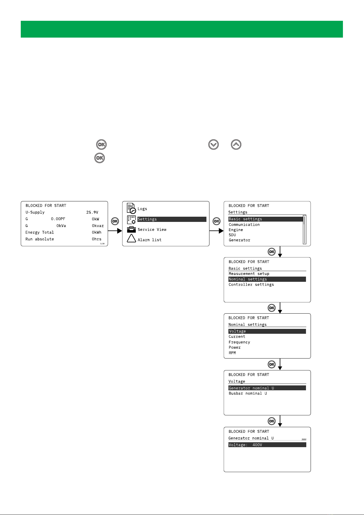
3.2 Settings menu
You can configure the controller in the settings menu and you can also find information, which is not available in the view menu.
From the view menu, push the button to find the settings menu. Use the and buttons to find the different settings
parameter and select with the button.
Settings menu example
This is an example of how to change the nominal voltage settings.
!
Push
Push
Push
Push
Push
Push
OPERATOR'S MANUAL 4189341314A EN Page 10 of 19
Other manuals for AGC 150
9
Table of contents
Other Deif Marine Equipment manuals


Popular Marine Equipment manuals by other brands


Clarion
Clarion GR10BT Owner's manual & installation manual

Raymarine
Raymarine Maxiview ST80 Owner's handbook

GUIDANCE MARINE
GUIDANCE MARINE 20- Series Installer's guide

Raymarine
Raymarine ST60 Tridata Owner's handbook

olympia electronics
olympia electronics ΒS-531/1/MAR quick start guide

Sonic
Sonic 2024 Operation manual