dB Technologies VIO L212 User manual

Manuale D’Uso
User Manual
Bedienungsanleitung
Caracteristique Techniques
Manual Del Usuario

2
VIO-L212 Cod. 420120270 REV. 0.1
EMI CLASSIFICATION
According to the standards EN 55032 and 55035 this equipment has been tested and found to comply with the
limits for a Class A digital device
Make sure that the loudspeaker is securely installed in a stable position to avoid any injuries or damages to
persons or properties. For safety reasons di not place one loudspeaker on top of another without proper fastening
systems. Before hanging the loudspeaker check all the components for damages, deformations, missing or
damaged parts that may compromise safety during installation. If you use the loudspeakers outdoor avoid spots
exposed to bad weather conditions.
Contact dBTechnologies for accessories to be used with the speakers. dBTechnologies will not accept any
responsibility for damages caused by inappropiate accessories or additional devices.
WARNING
Le avvertenze nel presente manuale devono essere
osservate congiuntamente al “MANUALE D’USO - Sezione2”.
The warnings in this manual must be observed
together with the “USER MANNUAL- Section 2”.
Die Warnungen in diesem Handbuch müssen in Verbindung mit
der“BEDIENUNGSANLEITUNG-Abschnitt2”beobachtetwerden”.
Les avertissements speciés dans ce manuel doivent être respectés
ainsi que les “CARACTERISTIQUES TECHNIQUES -Section 2”.
Las advertencias del presente manual se deben tener en cuenta
conjuntamente con las del “Manual del usuario” - Sección 2”.
FCC CLASS A STATEMENT ACCORDING TO TITLE 47, PART 15, SUBPART B,
§15.105
This equipment has been tested and found to comply with the limits for a Class A digital device, pursuant to part
15 of the FCC Rules.
These limits are designed to provide reasonable protection against harmful interference when the equipment is
operated in a commercial environment.
This equipment generates, uses and can radiate radio frequency energy and, if not installed and used in
accordance with the instructions, may cause harmful interference to radio communications.
Operation of this equipment in a residential area is likely to cause harmful interference in which case the user will
be required to correct the interference at his own expense.
Changes or modications not expressly approved by the party responsible for compliance could void the user’s
authority to operate the equipment.

IMPORTANT SAFETY INSTRUCIONS:
1. Read these instructions
2. Keep these instructions.
3. Heed all warnings.
4. Follow all instructions.
5. Do not use this apparatus near water.
6. Clean only with dry cloth.
7. Do not block any ventilation openings. Install in accordance with the manufacturer’s
instructions.
8. Do not install near any heat sources such as radiators, heat registers, stoves, or other
DSSDUDWXVLQFOXGLQJDPSOLíHUVWKDWSURGXFHKHDW
9. Do not defeat the safety purpose of the polarized or grounding-type plug. A polarazied
plug has two blades with one wider than the other. A grounding type plug has two
blades and a third grounding prong. The wide blade or the third prong are provided for
\RXUVDIHW\,IWKHSURYLGHGSOXJGRHVQRWíWLQWR\RXURXWOHWFRQVXOWDQHOHFWULFLDQIRU
replacement of the obsolete outlet.
10. Protect the power cord from being walked on or pinched particularly at plugs,
convenience receptacles, and the point where they exit from the apparatus.
11. 2QO\XVHDWWDFKHPHQWVDFFHVVRULHVVSHFLíHGE\WKHPDQXIDFWXUHU
12. 8VHRQO\ZLWKWKHFDUWVWDQGWULSRGEUDFNHWRUWDEOHVSHFLíHGE\WKH
manufacturer, or sold with the apparatus. When a
cart is used, use caution, when moving the cart/apparatus combination to
avoid injury from tip-over.
13. Unplug this apparatus during lightning storms or when unused for long periods of time.
14. 5HIHUDOOVHUYLFLQJWRTXDOLíHGVHUYLFHSHUVRQQHO6HUYLFLQJLVUHTXLUHGZKHQWKHDSSDUDWXV
has benn damaged in any way, such as power-supply cord or plug is damaged, liquid has
benn spilled or objects have fallen into the apparatusm the apparatus has been exposed
to rain or moisture, does not operate normally, or has been dropped.
$'',7,21$/6$)(7<,16758&7,216
• 1RQDNHGîDPHVRXUFHVVXFKDVOLJKWHGFDQGOHVVKRXOGEHSODFHGRQWKHDSSDUDWXV
• Do not use the apparatus in tropical climates


4
VIO-L212 Cod. 420120270 REV. 0.1
INDICE
Italiano
INDICE
1. INFORMAZIONI GENERALI ................................................................................................... 5
BENVENUTI!........................................................................................................................ 5
PANORAMICA INTRODUTTIVA .......................................................................................... 5
CARATTERISTICHE MECCANICHE ED ACUSTICHE ............................................................. 6
CARATTERISTICHE ACUSTICHE .................................................................................................................. 6
MECCANICA E DOTAZIONI PRINCIPALI..................................................................................................... 7
2. CONTROLLI LOCALI E CONNESSIONI................................................................................. 10
3. PREDIZIONE ACUSTICA E VERIFICA MECCANICA: DBTECHNOLOGIES COMPOSER .... 14
4. AURORA NET........................................................................................................................ 16
5. PARAMETRI DSP PRESET ..................................................................................................... 17
6. ACCESSORI, INSTALLAZIONE, CONFIGURAZIONE ........................................................... 18
FLY-BAR DRK-212 .............................................................................................................. 18
ADATTATORI FRA MODELLI ............................................................................................. 18
CARRELLI ........................................................................................................................... 18
PREDIZIONE ACUSTICA / VALIDAZIONE MECCANICA .................................................... 19
PREPARAZIONE DEL FLY-BAR E DEI MODULI .................................................................. 19
MONTAGGIO DEL LINE-ARRAY E CABLAGGIO ................................................................ 20
ESEMPI DI CONFIGURAZIONI MISTE ............................................................................... 23
ESEMPI DI CONFIGURAZIONI STACKED .......................................................................... 24
7. RISOLUZIONE DEI PROBLEMI ............................................................................................. 25
8. AGGIORNAMENTO DEL FIRMWARE.................................................................................. 26
9. SPECIFICHE TECNICHE ......................................................................................................... 27
GENERALE ................................................................................................................................................ 27
DATI ACUSTICI.......................................................................................................................................... 27
AMPLIFICATORE....................................................................................................................................... 27
PROCESSORE............................................................................................................................................ 28
INTERFACCIA UTENTE.............................................................................................................................. 28
INGRESSI ED USCITE ................................................................................................................................ 28
COMPATIBILITA’ SOFTWARE ................................................................................................................... 28
SPECIFICHE DI ALIMENTAZIONE (ASSORBIMENTO)............................................................................... 29
SPECIFICHE MECCANICHE ....................................................................................................................... 29

1100
380
330
4500
30
32
155
59 48,5
5
VIO-L212 Cod. 420120270 REV.0.1
1. INFORMAZIONI GENERALI
BENVENUTI!
PANORAMICA INTRODUTTIVA
Grazie per aver acquistato un prodotto progettato e sviluppato in Italia da dBTechnologies! Questo
line-array attivo, potente ed adatto ai live più impegnativi è frutto di una lunga esperienza nel campo della
diffusione sonora. Impiega soluzioni innovative ed ottimizzate in campo acustico ed elettronico, oltre che nella
ricerca dei materiali.
Il modulo line-array attivo a 3 vie VIO-L212 segna
una nuova tappa nel campo della ricerca ed
ottimizzazione per le applicazioni professionali
live indoor e outdoor di grandi dimensioni. Le
caratteristiche più salienti sono:
• ottimizzazione tra prestazioni acustiche full-range
e dimensioni
• sistema di appendimento a 3 punti per un
montaggio/smontaggio efciente
• linea di accessori professionali dedicati per la
movimentazione ed il montaggio
• sezione di amplicazione composta da 2
DIGIPRO G4 da 1600 W RMS ciascuno, controllati
da DSP a 32 bit (ltraggio FIR dedicato)
• tecnologia Floating ADC, sviluppata per un
perfetto isolamento da interferenze, rumori o
ronzii, dell’ingresso audio
• controllo da DSP e ltraggio in tempo reale con
ltri FIR
• rilanci di alimentazione, audio e di rete per un
cablaggio ottimizzato
• controllo RDNet on board, predisposizione per
protocollo AoIP Audinate DanteTM
• software predittivi e di gestione remota
(DBTECHNOLOGIES COMPOSER, EASE, EASE
FOCUS 3, AURORA NET)
Italiano
6
VIO-L212 Cod. 420120270 REV. 0.1
CARATTERISTICHE MECCANICHE ED ACUSTICHE
CARATTERISTICHE ACUSTICHE
Italiano
A
A
B
B
C
D
D
E
FF
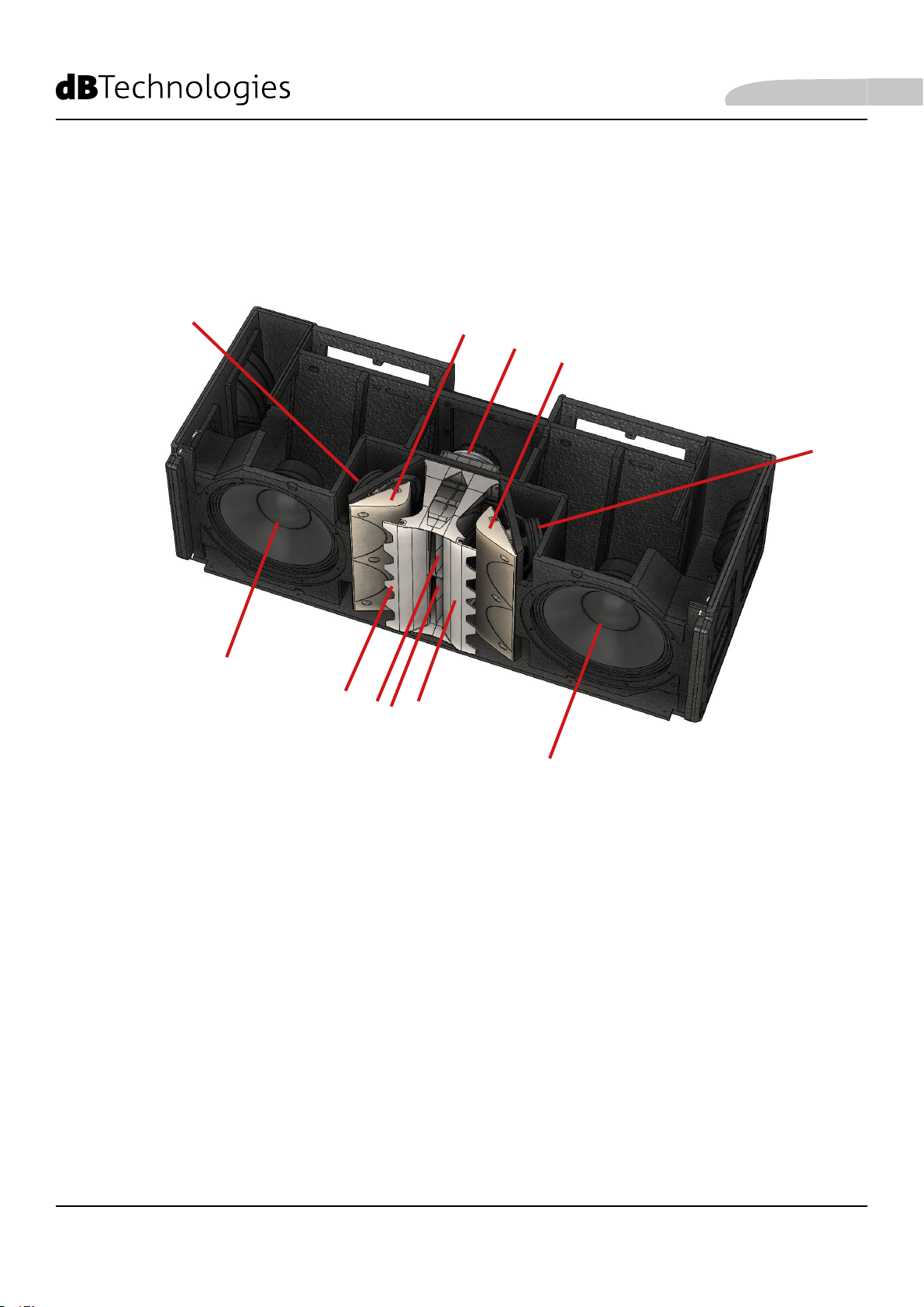
A-[LF] 2 Woofer in Neodimio di diametro 12”, voice coil da 3”(congurazione reex).
B - [MF] 4 Mid-Range in Neodimio di diametro 6.5”, voice coil da 2”.
C - [HF] 2 Compression Driver in Neodimio, bocca da 1.4”, bobina in Titanio da 3” (caricamento a tromba).
D-Phase plug con camera ottimizzata
E - Guide d’onda
F - Proli con andamento logaritmico della tromba
L’ottimizzazione acustica di VIO-L212 armonizza le prestazioni (SPL, risposta in fase e in frequenza, focus
sonoro) con le dimensioni e i vincoli meccanici di progetto.
In particolare:
• i phase plug [D] con camera ottimizzata aumentano la coerenza delle medie frequenze
• il posizionamento e la distanza dei trasduttori Mid-Range concorre a un focus sonoro e ad un ascolto
fuori asse nettamente deniti
• i proli con andamento logaritmico [F] della tromba, evitano tra l’altro, la creazione di riessioni costanti
(modi) ed aumentando la coerenza del comparto medie-alte
• le guide d’onda [F] controllano la direttività verticale delle alte frequenze
E

7
VIO-L212 Cod. 420120270 REV.0.1
MECCANICA E DOTAZIONI PRINCIPALI
Italiano
U
T
Z
Y
W
XZ
T
V
V
T - PIN DI FISSAGGIO ANTERIORI
U - STAFFE A SCOMPARSA PER
IL FISSAGGIO AD UN MODULO
SUPERIORE
V - SEDI PER IL FISSAGGIO AD UN
MODULO INFERIORE
W- STAFFA POSTERIORE
X- GIUNTO MOBILE
Y- PIN DI FISSAGGIO POSTERIORI
Z- RAIN COVER
Il sistema di ssaggio a 3 punti impiega, tramite l’utilizzo di pin:
• le staffe superiori U, sul lato frontale
• le sedi inferiori V, sul lato frontale
• la staffa W, con giunto X, sul lato posteriore.
Nelle immagini successive, per semplicità, non saranno più rafgurati i rain cover [Z].

8
VIO-L212 Cod. 420120270 REV. 0.1
Per il ssaggio di due moduli:
LATO ANTERIORE
1) Sul modulo Bestrarre verso
l’altole staffe U e ssarle con i
relativi pin.
2) Estrarre i pin T dal modulo A
3) Avvicinare i 2 moduli
inserendo le staffe U nelle
sedi V.
4) Inserire completamente i pin
T. In questo modo i moduli A
e B sul lato frontale risultano
bloccati.
LATO POSTERIORE
5) Sul modulo A sbloccare il
giunto X. Inserire quindi
il pin Y nel foro relativo
all’inclinazione desiderata.
I dettagli relativi a questa
operazione sono illustrati
nella pagina successiva.
Sono differenti a seconda
dell’installazione FLOWN o
STACK.
T
TU
U
X
W
Y
U
T
X
Y
W
A
B
A
B
V
Italiano
9
VIO-L212 Cod. 420120270 REV.0.1
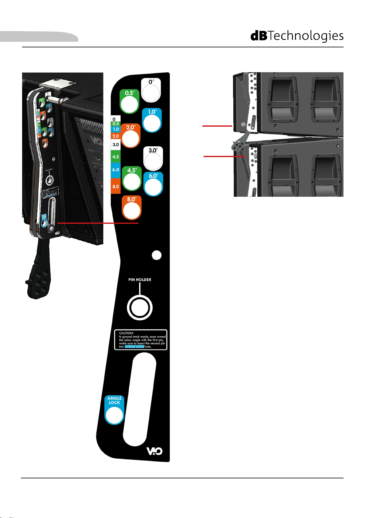
PIN 1
PIN 2
INSTALLAZIONE FLOWN
E’ necessario un solo pin (PIN 1) per ssare l’angolo
sul retro. I fori di inserimento della staffa W, con colori
differenziati, permettono le angolazioni: [0°, 0.5°, 1°, 2°,
3°, 4.5°, 6°, 8°]. L’asola della staffa consente di inserire i
pin senza dover sollevare il retro di VIO-L212.
INSTALLAZIONE STACKED
Sono necessari 2 pin (PIN1, PIN2) per ssare l’angolo
sul retro. Una volta inserito PIN1, come da procedura
FLOWN, si alza il retro di VIO-L212 nchè l’asola lo
permette e si ssa la posizione con il PIN2.
X
W
Italiano
Table of contents
Languages:
Other dB Technologies Recording Equipment manuals


