Daewoo DTC-1472 User manual


1
SPECIFICATIONS
Reception System 8-systems for TV standard broadcasting
-PAL B/G, SECAM B/G, PAL I, PAL H, PAL D/K
SECAM D/K, SECAM K1, NTSC-M
4 MODIFIED COLOR SYSTEMS for VCR playback only
-SECAM I, NTSC 4.43/5.5MHz, NTSC 4.43/6.0MHz,
NTSC 4.43/6.5MHz
6 SYSTEMS for Video Discs
-PAL 60Hz/5.5MHz, PAL 60Hz/6.0MHz
PAL 60Hz/6.5MHz, SECAM 60Hz/5.5MHz
SECAM 60Hz/6.5MHz
Power Requirements AC 90-260V, 50/60Hz
Power Consumption 75W(14 INCH) 85W(20 INCH)
Sound Output Power 3W+3W(14 INCH) 3W+3W(20 INCH)
Antenna lmpedance 75 ohm unbalanced
300 ohm balanced with supplied balun
Picture Tube Type A34 JLL90X01(14 INCH) A48JLL90X(20 INCH)
Screen Size 37cm(Diagonal :14 INCH) 51cm(Diagonal : 20 INCH)
Operating Frequencies Video IF 38.9MHz
Sound IF 33.4MHz, 32.9MHz, 32.4MHz, 34.4MHz
Channel Coverage VHF LOW E2-E4(EUROPE-B)
A02-A06(AMERICA-M)
R1-R5(OIRT-D)
VHF HIGH E5-E12(EUROPE-B)
A07-A13(AMERICA-M)
R6-R12(OIRT-D)
4-9(FOPTA-KI)
UHF E12-E26(EUROPE-G, K, K1)
A14-A79(AMERICA-M)
Cable Channels S1'-S31, S1-S20
Channel Indication ON-Screen Display
Tuning System 50 Channels electronic tuning
Video Input Terminal 1.0Vp-p, 75 Ohm unbalanced type(Phono pin type)
Audio Input Terminal 500m Vrms/30 Kohm(Phono pin type)
Dimension 44.6(W) x 33.8(H) x 38.6(D)cm (14 INCH)
57.6(W) x 45.8(H) x 46.2(D)cm (20 INCH)
Weight 11.3Kg(14 INCH) 19.2Kg(20 INCH)
Remote Control Unit Requires two 1.5V penlight batteries type AA size.

●Adequate ventilation must be provided to prevent heat building up inside of the unit.
Keep the inside of the unit free from foreign objects such as hairpins, nails, paper, etc.
Do not place the set into a bookcase or other enclosure in which it would be poorly
ventilated.
Do not place it on a carpet or bed as lower ventilation holes could be obstructed.
●Do not place liquids including flower vases and vessels filled with chemicals or water,
etc., on the top of the unit as liquid could get inside. If a hazardous object falls inside
of the unit, unplug it immediately and call a qualified technician for removal.
●Never allow cord to become knotted or tangled. Do not lengthen the cord.
When removing the power plug from the socket, always take hold on the plug, never
pull by the cord.
Place this unit on a flat, level surface
and in a dry area free from dust and
moisture. Do not place the unit in direct
sunlight, or where it would be affected by
smoke, steam, vibration or heat from
radiators. To prevent excessive internal
temperature rising, place the unit at least
15cm apart between it and surrounding
walls.
To prevent fire or shock hazard, do no expose this unit to rain or moisture.
2
IMPORTANT SAFEGUARDS
LOCATION
FIRE AND SHOCK PRECAUTIONS
15cm
minimum
WARNING

●Do not remove the backcover of the TV set. Accidental contact
with high voltage components could result in electric shock.
When internal adjustments are necessary, please contact your
service centre.
●If your set produces sound but no picture, or if it emits smoke or
produces a strange sound of smell, continuous operation is
dangerous. Immediately remove the power plug from the socket
and contact your service centre.
●During vacation or other occasions when you don't use the set for
an extended period, always make sure of switching off the MAIN
POWER SWITCH of the TV set and remove the power plug from
the socket.
Thank you for your purchase of this TV set. This model is a high-quality colour TV
designed and manufactured for excellent TV channels with ON-SCREEN indication of
channel number and volume up/down, colour up/down, bright up/down etc. with a
convenient remote control unit. It is also equipped with a programmable CLOCK/ON-
TIMER/OFF-TIMER function and Audio/Video input, output terminals. Please read this
instruction manual carefully in order to dbtain maximum performance from this receiver
for a long period of time.
3
WARNING

1
Antenna Terminal
2
Audio Input Terminal (Phono pin type)
3
Video Input Terminal (Phono pin type)
4
Audio Output Terminal = TV Audio Out (Phono pin type)
5
Video Output Terminal = TV Video Out (Phono pin type)
For reception of true colour reproduction, an effective antenna installation is the most
important. Please make sure that your antenna is correctly connected.
1. If you are located in a relatively strong signal area, you will be able to use the VHF
rod antenna. To connect the antenna, insert the plug of the VHF antenna into the TV
set antenna terminal.
2. When using an external antenna, the antenna is usually connected to the TV set by
means of a 75 ohm coaxial antenna cable. To make the connection, first attach a
suitable coaxial plug to the antenna cable and then insert the plug into the antenna
terminal on the rear of the set.
If your antenna system uses 300 ohm parallel feeder, connect the feeder to a 300
ohm → 75 ohm coversion plug and insert the plug into the TV set antenna terminal.
a) Coaxial plug (IEC-Type)
b) 300 ohm → 75 ohm converter plug (IEC-Type)
c) 75 ohm coaxial cable
d) 300 ohm parallel feeder
4
ANTENNA CONNECTION
VIDEO AUDIO
ANT
OUT
IN
2
45
3
1
The supplied rod antenna cannot be used to receive UHF
brodcasts. To receive UHF broadcasts, please use a UHF
antenna or VHF/UHF combination antenna.
NOTE
a
b
c
d
ANT

5
LOCATION OF CONTROLS
■FRONT VIEW
1
STAND-BY INDICATOR (STAND-BY)
2
ON-TIMER INDICATOR (ON-TIMER)
3
INFRARED SENSOR WINDOW (REMOTE SENSOR)
DTC-1472 DTC-2072
33
22
11

6
CONTROL BOX
1
MAIN POWER BUTTON
2
POWER BUTTON
3
TV / VIDEO BUTTON (TV/VIDEO)
4
MENU BUTTON
5
ENTER BUTTON (
Ê
)
6
VOLUME UP BUTTON ( VOL ▲) (CURSOR UP BUTTON)
7
VOLUME DOWN BUTTON ( VOL ▼) (CURSOR DOWN BUTTON)
8
PROGRAM UP BUTTON ( PR ▲) (DATA UP BUTTON)
9
PROGRAM DOWN BUTTON ( PR ▼) (DATA DOWN BUTTON)
1 3 5 7 9
2 4 6 8
MAIN POWER POWER MENU VOL PR
TV/ VIDEO ENTER
7
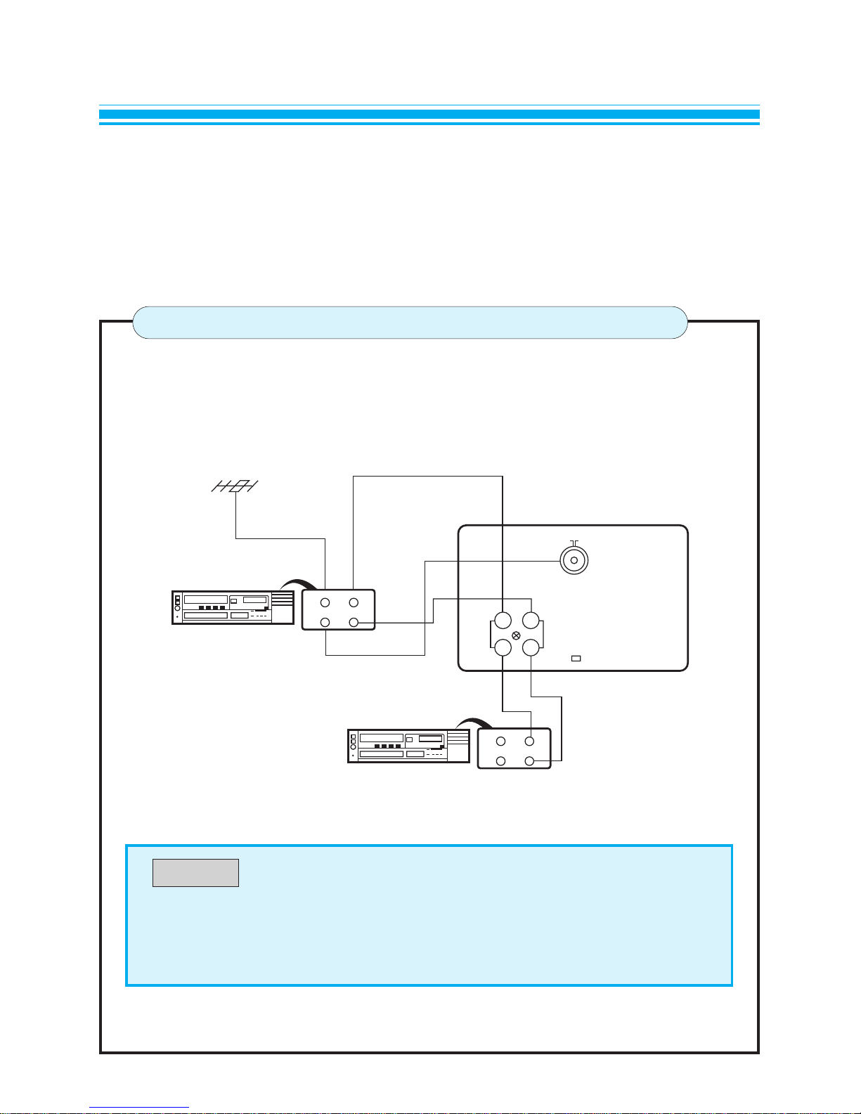
AV CONNECTIONS
CONNECTION OF THE VCR
● “Video out” of the terminal is RF signal.
● When receiving video signal, TV(RF) out operates equally with the video
system.
NOTE
This TV receiver is equipped with RCA JACK for your desired equipment to be connected.
VCR, video disc player, satellite receiver or other AV apparatus can be connected to the RCA
JACK on the rear panel of the TV receiver.
Please refer to the operation manual of your VCR for details.
VCR
REAR VIEW OF THE TV SET
ANT IN VIDEO OUT
AUDIO OUTOUT
VCR
ANT IN VIDEO IN
AUDIO INOUT
ANT
AUDIO
IN
OUT
VIDEO
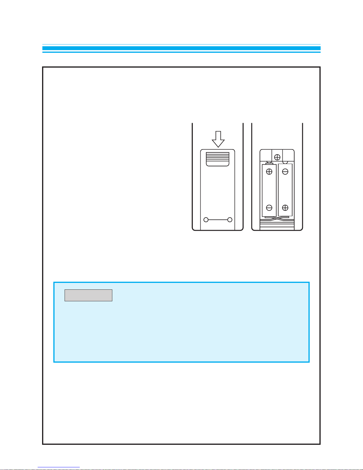
The remote control unit operates with two 1.5V size AA(penlight) batteries.
For battery installation or replacement;
1.Turn the remote control unit upside
down.
Press down on the battery compart-
ment grip and slide the cover in the
direction of the arrow.
2. Install the two batteries making sure
that battery polarity matches with the
(+), (-) marks inside of the battery
compartment.
Incorrect polarity could damage to the
unit.
3. Close the battery compartment cover.
8
BATTERY INSTALLATION
●The remote control unit is designed to operate within a distance of about 7
meters. If malfunction occurs even though you are within the effective
operating range, batteries may be weak and required replacement.
●Do not mix new and old batteries.
NOTE

9
REMOTE CONTROL UNIT
POWER TV USE PAGENO
110POWER
210MENU
310ENTER
416PR UP
DATA UP
516PR DOWN
DATA DOWN
616VOL DOWN
CURSOR DOWN
716VOL UP
CURSOR UP
817TV/VIDEO
918NORMAL
10 18RECALL
11 18QUICK VIEW
12 17MUTE
13 17SLEEP
TV/VIDEO 0
1
4
1- 2-
3- 4-
7
2
5
8
3
6
9
MENU
MUTE
SLEEP
Q/VIEWRECALLNORMAL
PR
E
VOL
PR
VOL
1
2
8
4
6
7
3
5
12
13
11
10
9
This manual suits for next models
1
Table of contents


