DAELIM DAYSTAR VL125E User manual

How to use this manual
This manual explains how to maintain the Daystar of the
DAELIM MOTOR CO., LTD.
Follow the maintenance schedule (Section 3) recommen-
dations to ensure that the vehicle is in peak operating
condition.
Section 1 through 3 apply to the whole motorcycle, while
sections 4 through 18 describe parts of the motorcycle,
grouped according to location.
Most sections start with an assembly or system
illustration, service information and trouble shooting for
the section. The subsequent pages give detailed
procedures.
If you don’t know the source of the trouble, go to section
20, trouble shooting.
All information, illustrations, directions and
specificiations included in this publication are based
on the latest product information avaliable at the time
of approval for printing.
DAELIM reserves the right to make changes at any
time without notice and without incurring any
obligation whatever.
No part of this publication may be reproduced wihtout
written permission.
Some drawings of this manual can be slightly different
from actual specification of model.
General Information
Lubrication
Maintenance
Fuel System
EMS(Engine Management System)
Engine Removal / Installation
Clutch / Gearshift
A.C. Generator / Starter Clutch
Cylinder Head / Valve
Cylinder / Piston
Crankcase / Transmission /
Crankshaft
Cooling System
Front Wheel / Front Fork
/ Steering
Rear Wheel / Rear Brake /
Suspension
Hydraulic Brake
Charging System / Battery
Ignition System
Electric Starter
Lights / Switches / Horn / Fuel Unit
Wiring diagram
Troubleshooting
Contents
Engine
FrameElectrical General
Seat / Exhaust Muffler

1. If the engine must be running to do some work, make sure the area is well-ventilated. Never run the
engine in an enclosed area. The exhaust contains poisonous carbon monoxide gas that may cause loss
of consciousness and lead to death.
2. The battery contains sulfuric acid(electrolyte) Contact with skin or eyes may cause severe burns. Wear
protective clothing and a face shield. If electrolyte gets on your skin, flush with water. If electrolyte
gets on your eyes, flush with water and call physician. Electrolyte is poisonous. Keep out of reach of
children.
3. Gasoline is extremely flammable and is explosive under certain conditions. Work in a well ventilated
area with the engine stopped. Do not smoke or allow flames or sparks in your working area.
4. Used engine oil may cause skin cancer if repeatedly left in contact with the skin for prolonged period.
Although this is unlikely unless you handle used oil on a daily basis, it is still advisable to thoroughly
wash your hands with soap and water as soon as possible after handling used oil.
Service Rules
1. Use genuine DAELIM or DAELIM recommended parts and lubricants or their equivalents.
2. Use the special tools designed for this product.
3. Install new gaskets, o-ring, piston pins, clips, cotter pins, etc. When reassembling.
4. When tightening a series of bolt or nuts, begin with the larger-diameter of inner bolts first, and tighten
to the specified torque diagonally, in incremental steps unless a particular sequence is specified.
5. Use only metric tools when servicing this motorcycle. Metric bolts, nuts, and screws are not
interchangeable with English fasteners.
6. Clean parts in cleaning solvent upon disassembly. Remove the cleanser with compressed air.
7. Lubricate any sliding surface before reassembly with recommended grease.
8. After reassembly, check all parts for proper installation and operation.
General Information
General Safety 1-1
Service Rules 1-1
Model Identification 1-2
Specification 1-3
Torque Values 1-5
Safety Notice 1-7
Tools / Tester gauge / Valve Seat Cut 1-8
Cable & Harness Routing 1-10
1. General Information
1-1
General Safety
!WARNING

1-2
General Information
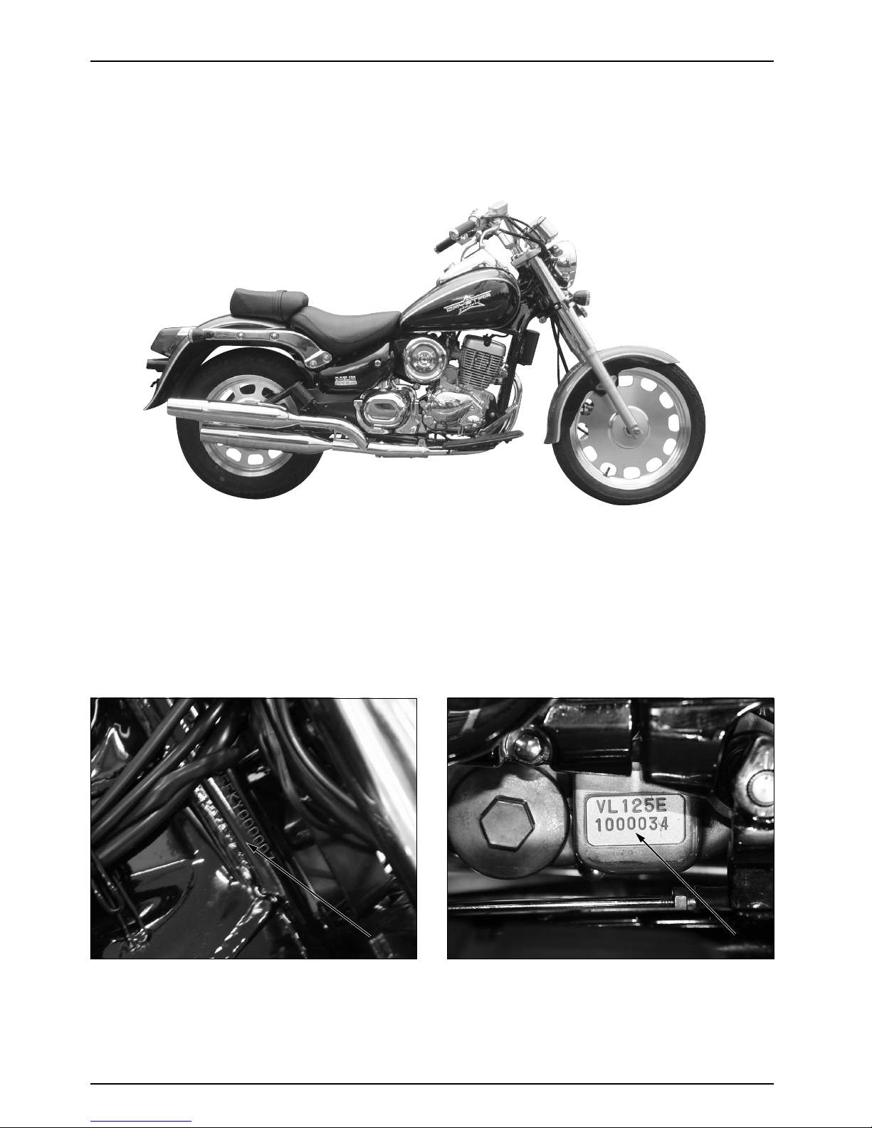
Model Identification
Frame No
Frame No
Frame No
Frame No
Frame No
Frame No
Frame No
Frame No
Frame No
Frame No
Frame No
Frame No Engine No
Engine No
Engine No
Engine No
Engine No
Engine No
Engine No
Engine No
Engine No
Engine No
Engine No
Engine No

1-3
General Information
Item Specifications
Overall Length 2,240mm
Overall Width 860mm
Overall Height 1,140mm
Dimensions
Wheel Base 1,505mm
Seat Height 720mm
Ground clearance 135mm
Dry Weight 147.5kgf
Curb Weight 344.9kgf
Type Double Cradle
Front Suspension Stroke Telescopic fork 140mm
Rear Suspension Stroke Swingarm 35mm
Front Tire Size 90/90 - 18 (Tubeless)
Rear Tire Size 130/90 - 15 (Tubeless)
Tire Pressure 1 Person Front 2.00kgf/cm2(200kPa)
Rear 2.00kgf/cm2(200kPa)
Frame
2 Person Front 2.00kgf/cm2(200kPa)
Rear 2.00kgf/cm2(200kPa)
Front Brake Hydraulic Disk
Rear Brake Drum Brake
Fuel Capacity 16.8
Fuel Reserve Capacity 4.3
Caster Angle 32
Trail Length 147mm
Front Fork Oil Capacity 280cm3
Type Oil / Air Cooled 4-stroke
SOHC Engine
Cylinder Number, arrangement 1 Cylinder, 15
Bore and Stroke 56.5 X 49.5mm
Displacement 124.1cm3
Comparison Ratio 11.5:1
Valve Train SOHC Chain Drive
Oil Capacity 1.2 After Disassembly
1.15 After Draining and Oil Filter Change
Engine
1.1 After Draining
Lubrication System Forced Pressure Splash Type
Air Cleaner Viscose Oil Wet Filter
Cylinder compression 14kgf/cm2(550rpm)
Intake Value Opens 6 BTDC
Closes 22 ABDC at 1.12mm Lift
Exhaust Value Opens 24 BBDC
Closes 4 BTDC at 1.12mm Life
Valve Clearance Intake 0.12 0.02mm(0.005 0.001 in)
(a cooling-off period)
Exhaust 0.12 0.02mm(0.005 0.001 in)
Engine Dry Weight 32.3kg
Specifications

1-4
General Information
Item Specifications
Clutch Hydraulic, Multi-plate
Transmission Type Constant Mesh Transmission
Primary Reduction 3.650(73/20)
Secondary Reduction 3.214(45/14)
Gear Ratio 1st 3.083(37/12)
Drive Train
Gear Ratio 2nd 1.882(32/17)
Gear Ratio 3rd 1.380(29/21)
Gear Ratio 4th 1.095(23/21)
Gear Ratio 5th 0.923(24/26)
Gearshift Pattern Left foot operated return system
1-N-2-3-4-5
Ignition TRANSISTER
Ignition Timing “F” Mark BTDC 18 2/1,600 150(rpm)
Battery Capacity 12V 10AH
Spark Plug CR9EH - 9
Spark Plug Gap 0.8 - 0.9mm
Fuse Capacity 30A, 15A
Starting System Starter Motor
Electrical
Headlight (High/Low Beam) 12V 60W/55W
Winker 12V 10W 4
Tail/Stop Lights 12V 5W/21W
Meter Light 12V 3W/3.4W(1.7W 2)
Neutral Indicator Lamp 12V 1.7W
High Beam Pilot Lamp 12V 1.7W
Malfunction Indicator Lamp 12V 1.7W

1-5
General Information
Item Q’ty Thread dia Torque Remark
Oil Filter Screen Cap 1 36 1.5(15)
Oil Filter Relief Valve Oval Screw 1 10 1.2(12)
Oil Filter Cover Socket Bolt 3 6 1.1(11)
Oil Pump Mounting Bolt 2 6 1.1(11)
Valve Adjusting Screw Lock Nut 4 5 1.1(11)
Drive Sprocket 2 6 1.2(12)
Engine Hanger Bolt(Front) 2 8 2.7(27)
Engine Hanger Bolt(Front 1, Rear 2) 3 10 4.9(49)
Clutch Lock Nut 1 16 6.5(65) Apply Engine Oil
Drum Stopper Arm Bolt 1 6 1.2(12)
Primary Drive Gear Bolt 1 16 6.5(65) Apply Engine Oil
R Crank Case Cover Bolt 11 6 1.1(11)
Gear Change Arm Bolt 1 6 1.2(12)
Flywheel Bolt 1 10 5.5(55) Apply Engine Oil
Starter Clutch Socket Bolt 3 8 3.2(32)
Apply a locking nut agent
Cam Chain Tensioner Pivot Bolt 1 8 1.1(11)
Spark Plug 1 10 1.1(11)
Cam Shift Holder 8mm nut 4 8 2.0(20) Apply Engine Oil
Cam Chain Tensioner Mounting Bolt 2
6 1.2(12)
Cam Chain Tensioner Sealing Screw
1 6 0.4(4)
Cylinder Head Cover Bolt 2 6 1.0(10)
Crank Shaft Hole Cap 1 30 0.8(8)
Timing Hole Cap 1 14 0.6(6)
L Crank Case Cover Bolt 7 6 1.1(11)
Main Shaft Bearing Setting Plate 2 6 1.2(12)
Apply a locking nut agent
Crank Case Bolt 11 6 1.1(11)
Starter Motor Terminal Nut 1 6 1.2(12)
Cylinder(Oil Through Bolt) 2 12 3.2(32)
Radiator(Oil Through Bolt) 2 12 3.2(32)
Torque Values
Engine
Item Q’ty Thread dia Torque Remark
Handle Holder Bolt 2 10 2.6(26)
Steering Stem Nut 1 22 7.4(74)
Steering top Thread Nut 1 22 1.8(18)
With a Starting torque
0.3(3)
With a Finishing torque
Front Fork Top Bridge Bolt 2 7 1.1(11, 8)
Front Fork Bottom Bridge Bolt 2 8 3.3(33)
Front Fork Socket Bolt 2 8 2.0(20)
Apply a locking nut agent
Front Fork Tube Cap 2 26 2.3(23)
Front Axle Nut 1 14 5.9(59)
Front Wheel Stud Bolt 5 6 0.6(6, 4.3)
Apply a locking nut agent
Ignition Switch Bolt 2 8 3.3(33)
Front Brake Disk Nut 6 8 4.2(42) Self lock nut
Frame
(mm)
kgf.m,(N.m)
(mm)
kgf.m,(N.m)

1-6
General Information
Torque specifications listed above are for important fastener. Other should be tighten to the standard
torque values below.
SH(Small Head): 6mm Bolt of 8mm Flange Head.
Type Torque Type Torque
kgf-m N.m kgf-m N.m
15mm Bolt, nut 0.45~6 4.5~6 5mm Screw 0.35~0.5 3.5~5
16mm Bolt, nut 0.8~1.2 8~12 6mm Screw&Flange 0.7~1.1 7~11
bolt (SH TYPE)
18mm Bolt, nut 1.8~2.5 18~25 6mm flange bolt, nut 1.0~1.4 10~14
10mm Bolt, nut 3.0~4.0 30~40 8mm flange bolt, nut 2.4~3.0 24~30
12mm Bolt, nut 5.0~6.0 50~60 10mm flange bolt, nut 3.5~4.5 35~45
Item Q’ty Thread dia Torque Remark
Brake Caliper Bracket Bolt 2 8 3.0(30)
Brake Caliper Bleed Valve 1 8 0.6(6)
Brake Pad pin Bolt 2 8 (1.8, 13)
Master Cylinder Reservoir Cap Screw
2 4 0.13(1.3)
Brake Hose Bolt 2 10 3.4(34)
Brake Lever Pivot Bolt 1 6 1.0(10, 7)
Brake Lever Pivot Lock Nut 1 6 1.0(10, 7)
Rear Axle Nut 1 14 8.8(88)
Final Driven Sprocket Nut 4 10 5.9(59)
Rear Brake Arm Bolt 1 6 1.0(10)
Rear Shock Absorber Upper Bolt 1 10 3.4(34)
Rear Shock Absorber Lower Bolt 1 10 3.4(34)
Rear Fork Pivot Bolt 1 12 4.5(45) Self lock nut
Rear Brake Pedal Bolt 1 8 2.2(22)
Chain Tensioner Flange Nut 1 8 3.6(36)
(mm)
kgf.m,(N,m)
1-7
General Information
!WARNING
Safety Notices
Following marks indicate some warnings and caution against some specific service methods.
The following symbols indicate needed lubrication steps, the changing of parts, and required specialized
tools, etc. when performing maintenance
Special greases, etc. that do not correspond to the above are indicated without using symbols.
Symbol Caution Symbol Caution
Mark Meaning Mark Meaning
Indicates a strong possibility of
severe personal injury or loss of
life if instructions are not
followed
Use recommended engine oil,
unless otherwise specified
Use molybdenum oil solution
(mixture of the engine oil and
molybdenum grease with the
ratio 1:1)
Use multi-purpose grease
(Lithium based multi-purpose
grease NLGI #2 or equivalent)
Use molybdenum disulfide
grease (containing more than
3% molybdenum disulfide,
NLGI #2 or equivalent)
Use molybdenum disulfide
paste containing more than
40% molybdenum disulfide,
NLGI #2 or equivalent)
Use silicone grease
Apply a locking agent. Use the
agent of the middle strength,
unless otherwise specified
Apply sealant
Replace the parts with new
ones before assembly
Use brake fluid, DOT3 or DOT4.
Use the recommended brake
fluid, unless otherwise specified.
Use Forkor Suspension Fluid
Use special tool
Use optional tool. These tools
are obtained as you order parts
Indicates reference page.
(Example: Refer to page 3-1)
Indicates a possibility of
personal injury or equipment
damage if instructions are not
followed.
Gives helpful information
NOTE
!CAUTION
O.P. TOOL
S TOOL
CUSHION
OIL

1-8
General Information
Tools
Special Common
Description
Reference section
Description
Reference section
Clutch Center Holder 6 Wrench, 8 9mm 3
Flywheel Puller 7 Adjusting Wrench, B 3
Lock Pin Puller Set 8 Float Level Gauge 4
Sliding shaft 8
Lock Nut Wrench, 20 24mm
6
Sliding Weight 8 Extension Bar 6, 13
Valve Guide Reamer 8 Fly Wheel Holder 6, 7
Universal Bearing Puller 10 Valve Spring Compressor 8
Bearing Remover Set, 15mm
10 Driver 10, 13, 14
Remover Assy, 15mm 10 Attachment, 32 35mm 10, 14
Remover Shaft, 15mm 10 Attachment, 42 47mm 10, 13, 14
Remover Head 10 Attachment, 62 68mm 10
Sliding Weight 10 Attachment, 72 78mm 10
Thread Adopter 10 Pilot, 15mm 10, 14
Assembly Shaft 10 Pilot, 20mm 10
Crank Case Assembly Color
10 Pilot, 35mm 10
Ball Race Driver 13 Pilot, 28mm 10
Steering Stem Driver 13
Lock Nut Wrench, 30 32mm
13
Fork Seal Driver 13 Attachment, 37 40mm 13
Steering Stem Socket 13 Pilot, 12mm 13
Snap Ring Pliers 15 Fork Seal Driver Body 13
Remover Head, 12mm 13
Bearing Remover Shaft 13, 14
Remover Head, 15mm 14
Rear Cushion Compressor 14
Attachment 14

1-9
General Information
Tester, Gauge
Compression Gauge
Digital Circuit Tester
Circuit Tester
Inspecion Adapter
Spark Adapter
3
16, 17
16, 17
17
17
RemarkDescription Reference section
Valve Seat Cut
Valve Seat Cutter 45
Valve Seat Cutter 35
Valve Seat Cutter 60
Cutter Holder 5mm
8
8
8
8
8
24.5mm IN, EX
23mm IN
20mm EX
22mm IN, EX
Use with Valve Seat
RemarkDescription Reference section
Table of contents
Other DAELIM Motorcycle manuals

DAELIM
DAELIM ROADWIN - User manual

DAELIM
DAELIM S3 User manual

DAELIM
DAELIM Daystar 250 User manual

DAELIM
DAELIM DAYSTAR FI User manual

DAELIM
DAELIM VJF125 User manual

DAELIM
DAELIM ROADWIN - User guide

DAELIM
DAELIM DAYSTAR - User manual

DAELIM
DAELIM VJF125 User manual

DAELIM
DAELIM VS125 User manual

DAELIM
DAELIM ROADWIN 125 FI User manual