CYP CSR-8PSU-5V User manual

CSR-8PSU-5V
8-Port 5V DC Power Manager
Operation Manual
Operation Manual


DISCLAIMERS
The information in this manual has been carefully checked and
is believed to be accurate. Cypress Technology assumes no
responsibility for any infringements of patents or other rights of third
parties which may result from its use.
Cypress Technology assumes no responsibility for any inaccuracies
that may be contained in this document. Cypress also makes no
commitment to update or to keep current the information contained
in this document.
Cypress Technology reserves the right to make improvements to this
document and/or product at any time and without notice.
COPYRIGHT NOTICE
No part of this document may be reproduced, transmitted,
transcribed, stored in a retrieval system, or any of its part translated
into any language or computer le, in any form or by any means—
electronic, mechanical, magnetic, optical, chemical, manual, or
otherwise—without express written permission and consent from
Cypress Technology.
© Copyright 2017 by Cypress Technology.
All Rights Reserved.
TRADEMARK ACKNOWLEDGMENTS
All products or service names mentioned in this document may be
trademarks of the companies with which they are associated.

SAFETY PRECAUTIONS
Please read all instructions before attempting to unpack, install or
operate this equipment and before connecting the power supply.
Please keep the following in mind as you unpack and install this
equipment:
• Always follow basic safety precautions to reduce the risk of re,
electrical shock and injury to persons.
• To prevent re or shock hazard, do not expose the unit to rain,
moisture or install this product near water.
• Never spill liquid of any kind on or into this product.
• Never push an object of any kind into this product through any
openings or empty slots in the unit, as you may damage parts
inside the unit.
• Do not attach the power supply cabling to building surfaces.
• Use only the supplied power supply unit (PSU). Do not use the PSU
if it is damaged.
• Do not allow anything to rest on the power cabling or allow any
weight to be placed upon it or any person walk on it.
• To protect the unit from overheating, do not block any vents or
openings in the unit housing that provide ventilation and allow for
sufcient space for air to circulate around the unit.
REVISION HISTORY
VERSION NO. DATE (DD/MM/YY) SUMMARY OF CHANGE
RDV1 01/08/17 Preliminary release
VS1 23/08/17 Final technical review
VS2 27/12/17 Updated diagrams
VS3 22/05/18 Updated section 3

CONTENTS
1. Introduction......................................................1
2. Applications.....................................................1
3. Package Contents ..........................................1
4. System Requirements......................................1
5. Features............................................................2
6. Operation Controls and Functions.................2
6.1 Front Panel ................................................. 2
6.2 Rear Panel.................................................. 3
6.3 RS-232 Protocol.......................................... 4
6.4 RS-232 and Telnet Commands ................ 4
6.5 Telnet Control ............................................ 6
6.6 WebGUI Control ........................................ 7
6.6.1 Status ................................................. 8
6.6.2 Device Settings ................................ 9
6.6.3 Schedule......................................... 10
6.6.4 System Settings............................... 11
7. Connection Diagram ....................................12
8. Specications ................................................13
9. Acronyms .......................................................13

1
1. INTRODUCTION
This 8-Port Managed 5V DC Power Supply is a DC power splitter which
can distribute up to 3 amps of 5 volt power to up to eight connected
devices via 2-pin terminal block connections (120 watts total across all
8 outputs). Ideal for professional applications, this unit provides direct
per-port power control via WebGUI, Telnet or RS-232. An integrated,
battery backed-up, clock allows for detailed power scheduling based
on a repeating daily/weekly schedule, or single events. Up to 2 fans
may be connected and their speed can be either automatically
controlled based on a detected temperature, or set to a single static
speed. Detailed status information about the power input, each
power output, current fan speed, and system temperature is provided
to give a comprehensive system overview.
2. APPLICATIONS
• Entertainment Rooms & Home Theaters
• Showrooms & Demo Rooms
• Lecture Hall Presentations
• Public Commercial Displays
• AV Equipment and Control Rooms
3. PACKAGE CONTENTS
• 1×8-Port 5V DC Power Manager
• 1×12V/12.5A DC Power Adapter
• 1×Power Cord
• 8×2-pin Terminal Block to 5V DC Power Adapter Cable
• 1×Fan Power/Control Cable
• 1×3.5mm to 9-pin D-sub Adapter Cable
• 1×Operation Manual
4. SYSTEM REQUIREMENTS
5V powered equipment requiring less than 15 watts of power using
2-pin 3.5mm terminal block terminated power cables.
2
5. FEATURES
• Power management system providing voltage-controlled current
(5V) on each output
• Battery backed up clock for scheduling power events
• Integrated WebGUI for control and power analysis
• Unit’s overall maximum power consumption is only 140 watts
• Supports 8 power output ports with professional 2-pin 3.5mm
terminal block connectors
6. OPERATION CONTROLS AND FUNCTIONS
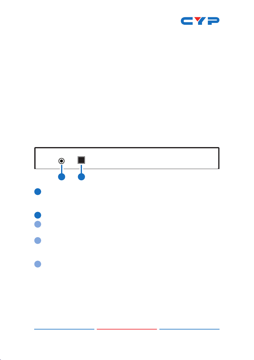
6.1 Front Panel
ISP/
RESET
RS-232
5V DC Power Manager
1 2
1RS-232: Connect directly to your PC/laptop using a 3.5mm mini-
jack to 9-pin adapter to send RS-232 commands to control the
unit.
2ISP/RESET: This button has multiple functions, see below.
2a ISP MODE: Press and hold this button while powering the unit on to
enter ISP mode.
2b FACTORY RESET: Press and hold this button for 5+ seconds, after the
unit is already powered on, to perform a full factory reset of the
unit.
2c REBOOT: Momentarily press this button, after the unit is already
powered on, to reboot the unit.
3
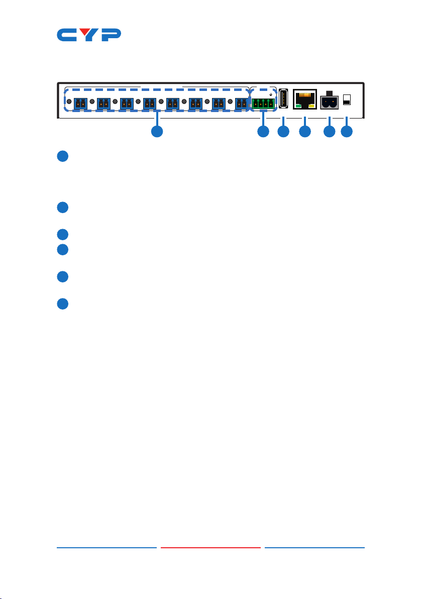
6.2 Rear Panel
-
+
DC 12V
SERV. CONTROL
FAN
5V POWER OUT
1
-
+
2
-
+
3
-
+
4
-
+
5
-
+
6
-
+
7
-
+
8
-
+
AB
12V
OFF
ON
1 2 3 4 5 6
15V POWER OUT & LEDs 1~8: Connect power cables with 3.5mm 2-pin
terminal blocks from units requiring 5V power. Up to 8 devices can
be powered. When power is available from a port, the associated
LED will be green. When a power port is disabled its LED will turn off.
212V FAN A/B: Connect to a dedicated dual-fan power and control
cable. Fan speed can be controlled via WebGUI, Telnet, or RS-232.
3SERV.: This slot is reserved for rmware update use only.
4CONTROL: Connect directly, or through a network switch, to your
PC/laptop to control the unit via Telnet/WebGUI.
5DC 12V: Plug the 12V DC power adapter into the unit and connect
it to an AC wall outlet for power.
6ON/OFF: Flip this switch to turn the unit ON or OFF after connecting
a 12V power source.
4
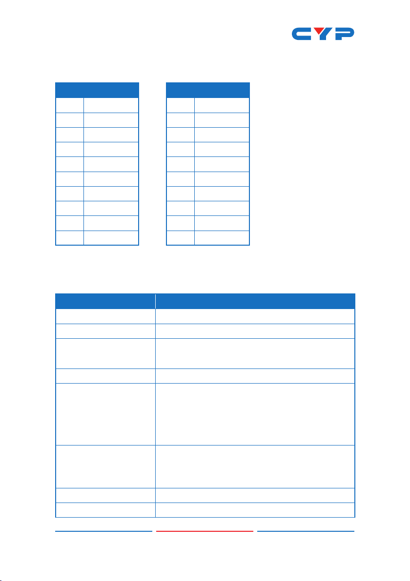
6.3 RS-232 Protocol
UNIT
►
◄
REMOTE SYSTEM
Baud Rate: 19200bps
Data Bits: 8
Parity Bits: None
Stop Bits: 1
Flow Control: None
Pin Denition Pin Denition
1 NC 1 NC
2TxD 2RxD
3RxD 3TxD
4 NC 4 NC
5 GND 5 GND
6 NC 6 NC
7 NC 7 NC
8 NC 8 NC
9 NC 9 NC
6.4 RS-232 and Telnet Commands
COMMAND DESCRIPTION AND PARAMETERS
HELP Show the full command list.
?Show the full command list.
HELP N1 Show a description of command N1.
N1 = {Command Name}
IPCFG Display the current IP conguration.
IPSTATIC N1 N2 N3 Set the full static IP conguration.
N1 = X.X.X.X [X = 0 ~ 255, IP Address]
N2 = X.X.X.X [X = 0 ~ 255, Netmask]
N3 = X.X.X.X [X = 0 ~ 255, Gateway]
IPDHCP N1 Enable or disable DHCP for obtaining the unit’s IP
conguration.
N1 = ON, OFF
VERSION Show the unit’s rmware version.
FADEFAULT Reset the unit to the factory defaults.

5
COMMAND DESCRIPTION AND PARAMETERS
REBOOT Reboot the unit.
PWR N1 N2 Enable or disable power output N1.
N1 = 1 ~ 8 [Port number]
N2 = ON, OFF
PWR N1 NAME N2 Rename power output N1.
N1 = 1 ~ 8 [Port number]
N2 = {Name String} [16 characters max]
PWR_STATUS N1 Show the current power state (volts, watts, amps)
of power output N1.
N1 = 1 ~ 8 [Port number]
TEMPERATURE Show details of the unit’s temperature and fan
control settings.
FAN_SET N1 Set non-“Auto Mode” fan speed or enable “Fan
Auto Mode”.
Available values for N1:
0 ~ 100 [Disable Fan Auto Mode
and set the fan speed to the
selected percentage]
AUTO [Enable Fan Auto Mode]
FAN_SET N1 N2 N3 Set the fan speed and temperature threshold for
the selected automatic speed tier.
Available values for N1:
AUTO_LOW [Auto fan setting to adjust]
AUTO_MID
AUTO_HIGH
N2 = 0 ~ 100 [Temperature threshold in
°C]
N3 = 0 ~ 100 [Fan speed in percent]
Note: Commands will not be executed unless followed by a carriage
return. Commands are not case-sensitive.
Table of contents
Other CYP Power Distribution Unit manuals


