
CYP CDPW-K1US User manual

CDPW-K1US
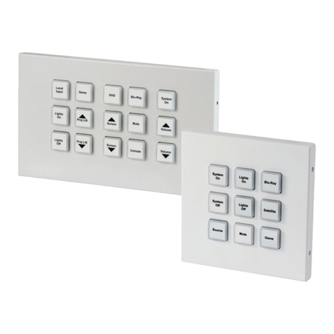
8-Button Wall Plate Control Keypad
Operation Manual
Operation Manual


DISCLAIMERS
The information in this manual has been carefully checked and
is believed to be accurate. Cypress Technology assumes no
responsibility for any infringements of patents or other rights of third
parties which may result from its use.
Cypress Technology assumes no responsibility for any inaccuracies
that may be contained in this document. Cypress also makes no
commitment to update or to keep current the information contained
in this document.
Cypress Technology reserves the right to make improvements to this
document and/or product at any time and without notice.
COPYRIGHT NOTICE
No part of this document may be reproduced, transmitted,
transcribed, stored in a retrieval system, or any of its part translated
into any language or computer le, in any form or by any means—
electronic, mechanical, magnetic, optical, chemical, manual, or
otherwise—without express written permission and consent from
Cypress Technology.
© Copyright 2011 by Cypress Technology.
All Rights Reserved.
Version 1.1 August 2011
TRADEMARK ACKNOWLEDGMENTS
All products or service names mentioned in this document may be
trademarks of the companies with which they are associated.

SAFETY PRECAUTIONS
Please read all instructions before attempting to unpack, install or
operate this equipment and before connecting the power supply.
Please keep the following in mind as you unpack and install this
equipment:
• Always follow basic safety precautions to reduce the risk of re,
electrical shock and injury to persons.
• To prevent re or shock hazard, do not expose the unit to rain,
moisture or install this product near water.
• Never spill liquid of any kind on or into this product.
• Never push an object of any kind into this product through any
openings or empty slots in the unit, as you may damage parts
inside the unit.
• Do not attach the power supply cabling to building surfaces.
• Use only the supplied power supply unit (PSU). Do not use the PSU
if it is damaged.
• Do not allow anything to rest on the power cabling or allow any
weight to be placed upon it or any person walk on it.
• To protect the unit from overheating, do not block any vents or
openings in the unit housing that provide ventilation and allow for
sufcient space for air to circulate around the unit.
REVISION HISTORY
VERSION NO. DATE (DD/MM/YY) SUMMARY OF CHANGE
VR0 16/10/15 First release
VR1 17/12/15 Revise Relay output specication

CONTENTS
1. Introduction............................................ 1
2. Applications........................................... 1
3. Package Contents ................................ 1
4. System Requirements............................ 1
5. Features.................................................. 2
6. Operation Controls and Functions....... 2
6.1 Front Panel ........................................2
6.2 Rear Panel.........................................3
6.3 Telnet Commands............................3
6.4 Software Application.......................5
6.5 Telnet Control ...................................6
6.6 WebGUI Control ...............................8
6.6.1 Macro Settings ........................8
6.6.2 Extension Macro....................11
6.6.3 Command Settings...............11
6.6.4 Schedule................................12
6.6.5 Network Settings ...................13
6.6.6 System Settings......................14
6.6.7 Time Settings..........................14
7. Connection Diagram .......................... 15
8. Specications ...................................... 16
9. Acronyms ............................................. 16

1
1. INTRODUCTION
The Wall-Plate Control System box is a fantastic and useful design for
system installer and smart home user. With 8 direct macro command
buttons and extra 8 macro commands in WebGUI control which
allows up to 16 commands to be execute within one push and a
total of 128 commands capacity inside this box that can bring out
a set of scenes in a seconds. Soft and colorful LED design tting all
environment purpose and PoE (Power over Ethernet) function ease
power supply issue without extra DC power burden. Further, relay
outputs design and scheduling function control settings can trigger
master switch or any main switch of the installation environment that
brings the world of control to whole.
2. APPLICATIONS
• Smart Home Installation
• Control Center
• Functional Room
• Show Room
• Ballroom
3. PACKAGE CONTENTS
• 1×Wall Plate Control System
• 1×USB Type A to Mini USB OTG Connector
• 2×3.5mm Terminal Block Pitch
• 1×5 V/2.6 A Power Adaptor
• 1×Button Stickers (28 pcs)
• 1×Operation Manual
4. SYSTEM REQUIREMENTS
Active internet connection from Hub or Router and output to DC
controllable device.

2
5. FEATURES
• 8 macro buttons and extra 8 macro buttons in WebGUI with up to
128 commands to implant for control system
• Supports Relays to control on/off of other devices
• Supports Scheduling control system and settings
• Supports scheduling memory over power blackout up to 48hrs
• Supports Key Pad, Telnet and WebGUI controls
• Supports PoE function or DC power supply selection
• US 1 Gang wall plate design with adjustable LED dim light
• Multiple uses for home, hotel room central control or conference
room and etc.
6. OPERATION CONTROLS AND FUNCTIONS
6.1 Front Panel
Source
4
Source
3
Source
2
All
Off
Source
1
All
On
Vol+
Vol
-
1
11~8 Macro Buttons: Each buttons has 2 colors of LEDs adjustable
from dim 0~100% and can be insert up to 16 commands. Further
detail settings, please refers to section 6.6 WebGUI control.

3
6.2 Rear Panel
DC 5V
+
Control
-
Relay
Out
1 32
1RELAY OUT: Connect with device that supports DC 0~24V/5A
power or signal that supports relay function.
2Control: Connect from PC/Laptop with active internet service or
Telnet or WebGUI control with RJ-45 terminated cable. This slot
supports PoE PD 48V function which means when the connected
server/Hub support PSE 48v it can be powered without DC supply
connection.
3DC 5V: Plug the 5V DC power adaptor included in the package
and connect to AC wall outlet for power supply.
6.3 Telnet Commands
COMMAND DESCRIPTION PARAMETER
IPCONFIG Display the current IP
congure
NONE
SIPADDR XXX.
XXX.XXX.XXX
Set ethernet IP address XXX=0~255
SNETMASK XXX.
XXX.XXX.XXX
Set ethernet net mask XXX=0~255
SGATEWAY XXX.
XXX.XXX.XXX
Set ethernet gateway XXX=0~255
SIPMODE N Set ethernet IP mode N=STATIC/DHCP

4
COMMAND DESCRIPTION PARAMETER
VER Show unit rmware version NONE
FADEFAULT All congure and macro
set to factory default
NONE
ETH_FADEFAULT All ethernet congure set
to factory*
NONE
REBOOT System reboot NONE
HELP Show command list NONE
HELP N Show descript of
command
N : COMMAND NAME
RELAY N N1 Relay control N(PORT)=1
N1=OPEN/CLOSE/TOGGLE
LEDBLUE N N1 Led blue backlight control N(LEN NO.)=1~8
N1=% (0-100)
LEDRED N N1 Led red backlight control N(LEN NO.)=1~8
N1=% (0-100)
LEDBLUES N All blue led backlight
control
N=% (0-100)
LEDREDS N All red led backlight
control
N=% (0-100)
LEDSHOW N Led dimming mode control LEDSHOW N
N=ON/OFF/TOGGLE
BACKLIGHT N All led backlight control N=% (0-100)
KEY_PRESS N
RELEASE
KEY_PRESS N
HOLD
Key press trigger type KEY_PRESS N RELEASE
N=PORT NUMBER
KEY_PRESS N HOLD
N=PORT NUMBER
MACRO N Macro setting MACRO RUN N N=MACRO
ID (1~16)
MACRO STOP
Note: *Any commands will not be executed unless followed by a
carriage return. Commands are case-insensitive.

5
6.4 Software Application
Please download the software from www.cypress.com.tw with le
name CDPS V2.000 and save it in a directory where you may use it
later.
Connect the Control System with PC/Laptop through the Ethernet port
of an active network system and open the CDPS V2.000 application.
Click on Find Devices on Network and a list of the devices connected
to the Control System will show up.
Note: The default IP setting is 192.168.1.50 and set the Static IP or DHCP
via IP mode of CDPS V2.000. Click ‘Save’ then ‘Reboot’ for loading
the new IP address.
Then user may use the IP Address to nd the control device through
Telnet or WebGUI tools.
Table of contents
Other CYP Keypad manuals


Popular Keypad manuals by other brands


Chamberlain
Chamberlain KPR2000 Installation setup manual

Aeware
Aeware k-35 Series Quick reference card

Aritech
Aritech CS-175 Series user guide

GE
GE NetworX NX-1600E Series user manual

Lenze AC Tech
Lenze AC Tech MC SERIES installation instructions

Burg Wächter
Burg Wächter secuENTRY 7711 operating instructions


