Cub Cadet CC-4624V2 User manual

READ AND FOLLOW ALL SAFETY RULES AND OPERATING
INSTRUCTIONS BEFORE USING THIS EQUIPMENT
CC-4624V2
24 cu ft LA
WN SWEEPER
U.S. Patent No. 7,610,646
6004282 - REV B 09/19

Read and understand all safety rules and operating instructions before using this
tractor attachment.
Follow all safety rules and operating instructions provided by your tractor's
manufacturer when using attachment.
Never allow children or untrained persons to operate tractor or attachment.
Reduce tractor speed to slowest setting when towing or operating on slopes.
Operate up and down slopes, never across the face of slopes.
Do not carry passengers on tractor or attachment.
Avoid sudden turns or maneuvers.
Use caution when backing up to prevent damaging attachment.
Do not tow attachment on public roadways.
Do not remove warning decals from product.
Check product for worn, loose, or damaged parts before each use. If any damage
is present, repair the product before using.
Check product for loose or missing fasteners before each use. Tighten or replace
fasteners as needed before using.
Do not fasten rope to any part of your body or clothing.
Do not hold rope while tractor and Lawn Sweeper are in motion.
Do not use Lawn Sweeper near fire or smoldering debris.
Always fasten rope to tractor to avoid contact with wheels and brushes.
Always empty hopper before storing to avoid spontaneous combustion of contents.
Do not exceed tractor speed of 6 miles per hour when towing or operating Lawn
Sweeper.
This is the safety alert symbol. It is used to alert you to
potential personal injury hazards. Obey all safety messages
that follow this symbol to avoid possible injury or death.
1
Safety Rules

If this product fails due to a defect in material or workmanship within THREE YEARS from the
date of purchase, we will at our option, only with receipt of purchase, repair or replace it free of
charge. This warranty excludes tires, wheels, brushes and bag, which are expendable and
become worn during normal use.
This warranty does not cover:
Repairs necessary because of operator abuse or negligence.
•
Equipment used for commercial or rental purposes.
•
Paint that is worn or faded due to normal use or exposure.
•
To arrange for product repair visit
ohiosteel.com/customer-support
and fill out the warranty
repair form. You can also call 1-800-652-2321, ext. 212 to speak to our Customer Service Team
This warranty gives you specific legal rights, and you may also have other rights which may vary
from state to state. This warranty applies only while this product is in use in the United States.
IF YOU ARE MISSING PARTS
DO NOT RETURN TO STORE
Email [email protected] or call 1-800-652-2321, ext. 212
Before you call,please email our customer service team at
with the following
:
A description of the issue you are having
1.
Photos of the issue that include an overall view and detailed view from
2.
multiple angles
If applicable, a short video showing the issue
3.
Replacement Parts:
You can place your parts order online at ohiosteel.com/partsstore
You can also reach our Customer Service Department at 1-800-652-2321, ext. 212
•
If you are ordering replacement part(s) for your product, please note that some parts are
•
only available as a repair kit.
AttachReceipt Here:
2
Warranty

38
(x1)
41
(x2)
44
(x1)
43
(x1)
37
(x2)
10
(x4)
12 & 49
(x7)
48
(x2)
50
(x1)
40
(x2)
39
(x2)
(x1)
45
(x2)
46
(x2)
42
(x1)
6
(x2)
7
(x4)
8
(x4)
9
(x4)
11
(x1)
13
(x1)
14
(x1)
15
(x1)
47
(x2)
52
(x1)
TOOLS REQUIRED FOR ASSEMBLY:
9/16" Open End Box Wrench
•
NOTE: Hardware shown to scale
3
Carton Contents
10 96
8
7
13
14
13
DETAIL Q
SCALE 1 : 2
34
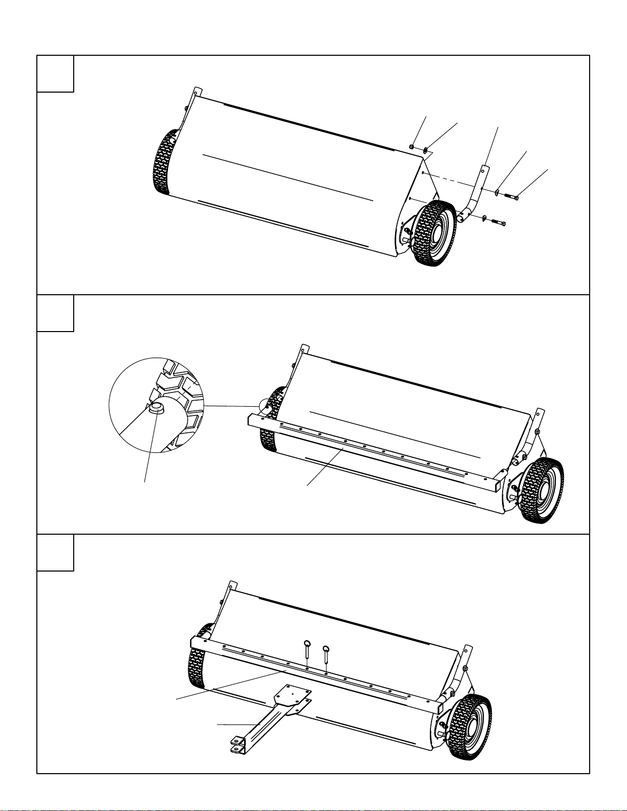
Attach Hitch Mount Tubes (6) to Sweeper Assembly and tighten hardware.
Attach Hitch Cross Tube Assembly (13) by depressing snap buttons and
insterting into Hitch Mount Tubes (34).
Install Hitch Assembly (14) using tethered quick release pins in desired
position on Hitch Cross Tube Assembly (13).
DO NOT OVERTIGHTEN.
4
Assembly Instructions
1
3
2

Shown Installed:
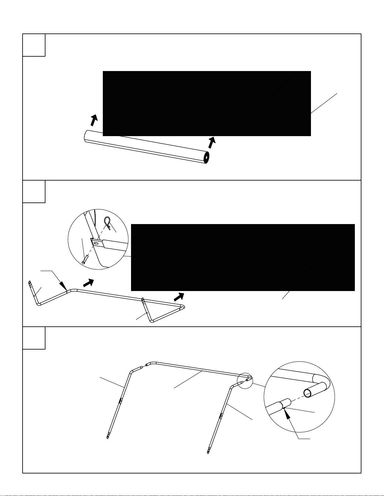
Insert Bottom Frame Tubes (39) into Center Frame Tube (41) and snap into
position. (Note that snap buttons are oriented up)
15
R
DETAIL R
SCALE 1 : 5
39
39
41
DETAIL S
SCALE 1 : 2
Snap Button
UP
51
First remove factory hand tightened nuts from studs. Use nuts to attach
Height Adjustment Handle (15) Using a 9/16" Open End Box Wrench.
5
Assembly Instructions
4
5
37
41
M
46
49
37
41
40
40
DETAIL D
SCALE 1 : 4
Snap Button
DOWN
51
Snap Button
UP
Frame into Hopper
39
39
DETAIL M
SCALE 1 : 6
46 49
Unroll and flatten hopper bag (38) from shipping state. Then, slide
Hopper Stop Bar (42) into pocket of Hopper Bag as shown.
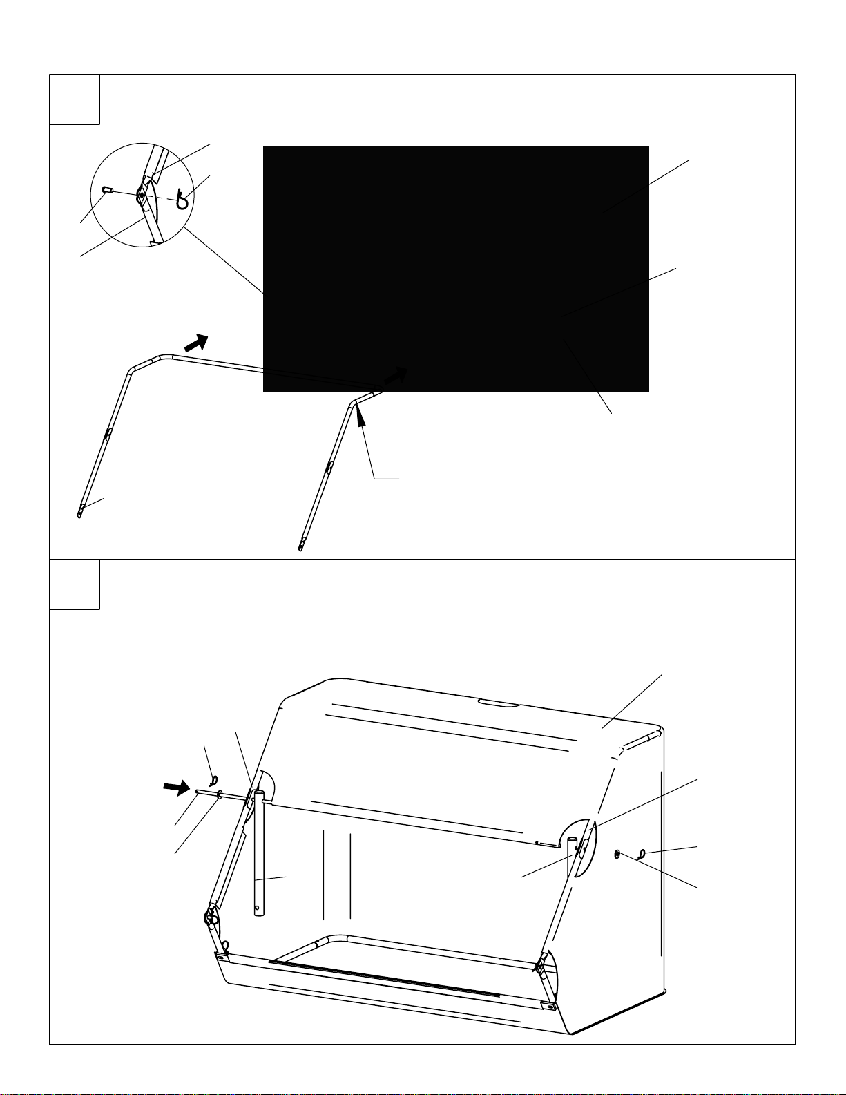
Insert Top Frame Tubes (40) into Center Frame Tube (41) and snap into position.
(Note that snap buttons (51) are oriented down)
Unroll Hopper Bag
38
44
First, place bottom frame assembly into bottom of Hopper Bag (38).
Second, Install Clevis Pins (46) through Hopper Bag (38), Hopper Stop Bar (42), and
Bottom Frame Tubes (39) then secure with Hairpins(49).
6
Assembly Instructions
6
8
7
X
44
48
37
49
42
47
37 37
49
47
40
38
40
Snap Button
Down
39
DETAIL X
SCALE 1 : 9
45
49
39
40
First, Place top frame assembly into Hopper Bag (38). Second, Install
Clevis Pins (45) through Top Frame Tubes (40) and Bottom Frame Tubes (39)
and secure with Hairpins (49).
Slide Hopper Pivot Rod (43) through Top Frame Tube (40) and Connecting Tube (37),
then through pocket of Hopper Bag (38), and then through
both Connecting Tube (37) and Top Frame Tube (40) on other side.
Secure both ends with Washer (47) and Hairpin (49).
Frame into Hopper
45
49
38
7
Assembly Instructions
9
10

38
42 41
Velcro Tab
38
DETAIL E
SCALE 1 : 2
41 42
G
DETAIL G
SCALE 1 : 4
Opening
R
DETAIL R
SCALE 1 : 1
T
DETAIL T
SCALE 1 : 1
Unscrew Thumb Screw from Tension Tube Assembly (44). Next, Hold Hopper Bag (38) open
and carefully insert Tension Tube Assembly (44) through opening in Hopper Bag and into hole
in bottom Center Frame Tube (41). Pull top Center Frame Tube over
tension tube and align holes.
Insert thumb screw that came with Tension Tube Assembly (44) through
top Center Frame Tube (41) and screw into top of Tension Tube.
Secure Hopper Bag around Top Frame Tubes with Velcro tabs.
SHOWN INSTALLED
SHOWN INSTALLED
8
Assembly Instructions
11
12
37
37
6
6
48
Do NOT fasten rope to any
part of your body or clothing.
5041
DETAIL V
SCALE 1 : 4
48
52
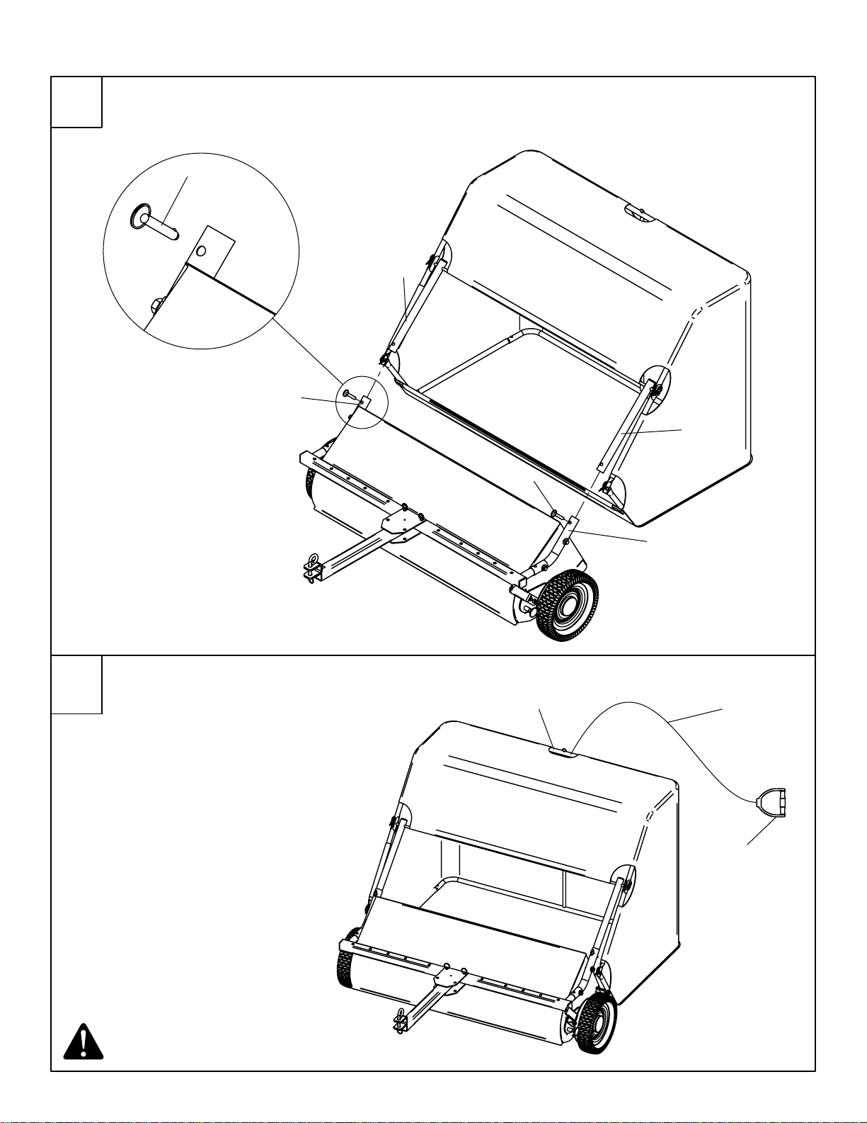
Insert Connecting Tubes (37) into Hitch Mount Tubes (6) and secure with
Quick-Release Pins (48). Install Hitch Pin (11) and secure with Hairpin(12).
Install handle (52) and tie Dump Rope (50) securely around exposed section
of Center Frame Tube(41).
9
Assembly Instructions
13
14
Table of contents
Other Cub Cadet Lawn Sweeper manuals


Popular Lawn Sweeper manuals by other brands


Agri-Fab
Agri-Fab 26" Leaf/Lawnsweeper 45-02181 owner's manual

Nordic
Nordic WS-L0118 operating manual

Smithco
Smithco 72-000-A Operator's manual

Parker
Parker Suburbanite 895803 Owner/Operator & Parts Manual

Agri-Fab
Agri-Fab 45-0290 owner's manual

Agri-Fab
Agri-Fab 26" Leaf/Lawnsweeper 45-02181 owner's manual