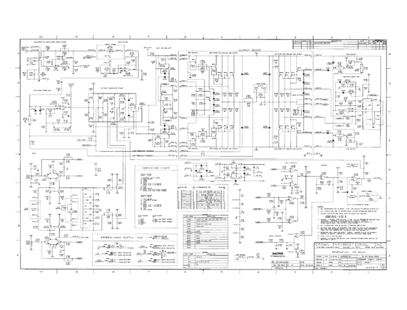
Crown FM1000A User manual

i
FM1000A
RF Amplifier Package
User's Manual
©2005Crown Broadcast, a division of International Radio and Electronics, Inc.
25166 Leer Drive, Elkhart, Indiana, 46514-5425 U.S.A.
(574) 262-8900
®

ii
Revision Control
Revision Print Date
Initial Release (Rev. 0) 900413-1 November 1998
Revision 1April 2002
Important Notices
©2005, Crown Broadcast, a division of International Radio and Electronics, Inc.
All rights reserved. No part of this publication may be reproduced, transmitted,
transcribed, stored in a retrieval system, or translated into any language in any
form by any means without the written permission of Crown International, Inc.
Printed in U.S.A.
Crown attempts to provide information that is accurate, complete, and useful.
Should you find inadequacies in the text, please send your comments to the
following address:
International Radio and Electronics
25166 Leer Drive, P.O. Box 2000
Elkhart, Indiana, 46515-2000 U.S.A.

iii
ContentsContents
ContentsContents
Contents
Section 1—Getting Acquainted
1.1 Your Amplifier Package .......................................................................................1–2
1.2 Amplifier Package Specifications.........................................................................1–3
1.3 Safety Considerations..........................................................................................1–4
1.3.1 Dangers ............................................................................................................1–4
1.3.2 Warnings ..........................................................................................................1–4
1.3.3 Cautions ...........................................................................................................1–4
Section 2—Installation
2.1 Operating Environment .....................................................................................2–2
2.2 Tools Required..................................................................................................2–2
2.3 Unpacking.........................................................................................................2–2
2.4 Preinstallation...................................................................................................2–3
2.4.1 Power Amplifier Modules .............................................................................2–3
2.4.2 Hubble Twist Lock® Connector Wiring ........................................................2–4
2.5 Installation ........................................................................................................2–5
2.6 Remote I/O Connection.....................................................................................2–6
Section 3—Operation
3.1 Initial Power-up Procedures..............................................................................3–2
3.2 Power Switches ................................................................................................3–4
3.2.1 AC Input Circuit Breaker ...............................................................................3–4
3.2.2 DC Power Switch..........................................................................................3–5
3.2.3 Interlock Switch............................................................................................3–5
3.3 Digital Multimeter .............................................................................................3–6
3.4 Fault Indicators .................................................................................................3–7
3.5 Fuse Indicators .................................................................................................3–8
Section 4—Principles of Operation
4.1 PA1000 Power Amplifier...................................................................................4–2
4.1.1 Power Modules ............................................................................................4–2
4.1.2 Power Combiner Board ................................................................................4–2
4.1.3 Backplane Assembly.....................................................................................4–3
4.1.3.1 Backplane DC Interconnect Board ........................................................4–3
4.1.3.2 Input Divider Board...............................................................................4–3
4.1.3.3 Output Combiner Board........................................................................4–3
4.1.4 Output Filter & Reflectometer.......................................................................4–3
4.1.5 Metering and Control Board .........................................................................4–4
4.1.6 DC Fuse and Power Distribution Board ........................................................4–4
4.1.7 Cooling Fans.................................................................................................4–4

iv
4.2 PS1000 Power Supply ......................................................................................4–4
4.2.1 AC Input Board .............................................................................................4–5
4.2.2 PFC (Power Factor Correcting) Switching Board ..........................................4–5
4.2.3 DC Output Board ..........................................................................................4–6
4.2.4 Cooling Fans.................................................................................................4–6
Section 5—Troubleshooting
5.1 Troubleshooting Flow Chart Analysis................................................................5–2
5.2 Digital Multimeter Parameters ..........................................................................5–3
5.2.1 In Ref (Input Drive Reference)......................................................................5–3
5.2.2 SWR (Standing Wave Ratio) ........................................................................5–3
5.2.3 ALC (Automatic Level Control) .....................................................................5–3
5.2.4 Power Out ....................................................................................................5–3
5.2.5 PA Temp .......................................................................................................5–4
5.2.6 PA Voltage ....................................................................................................5–4
5.2.7 Tot Current ...................................................................................................5–4
5.2.8 PA1–8...........................................................................................................5–4
5.3 Fault Indicators .................................................................................................5–5
5.3.1 Antenna ........................................................................................................5–5
5.3.2 RF Drive........................................................................................................5–5
5.3.3 PA Temp .......................................................................................................5–5
5.3.3.1 Potential Causes for Non-functioning Cooling Fans..............................5–5
5.3.4 PA DC ...........................................................................................................5–6
5.3.5 Multiple Indicators........................................................................................5–6
Section 6—Reference Drawings
6.1 Views ................................................................................................................6–2
6.2 Diagrams and Schematics ................................................................................6–3
Section 7—Service and Support
7.1 Service..............................................................................................................7–2
7.2 24–Hour Support..............................................................................................7–2
7.3 Spare Parts .......................................................................................................7–2
Glossary
Index

Getting Acquainted 1–1
I
INFORMATION
Section 1—Getting Acquainted
This section provides a general description of the FM1000A
power amplifier system and introduces you to safety conventions
used within this document. Review this material before install-
ing or operating the amplifier and power supply.

FM1000A User’s Manual
I
1–2
1.1 Your Amplifier Package
The FM1000A is a highly efficient amplifier package designed to set a new standard
in FM transmitter design offering modularity, ease of use, and long-term reliabil-
ity. The FM1000A package includes a PA1000 amplifier, PS1000 power supply, and
an FM1K accessory pack.
The PA1000 broadband amplifier requires no tuning and typically provides 80% RF
efficiency across the band. The PS1000 power supply is power factor corrected and
90% efficient. Modern MOSFET technology ensures high AC to RF efficiency
(better than 70% overall) and long-term reliability. The unmatched efficiency of
this power amplifier significantly improves your bottom line by providing cooler
operation and lower power costs.
These modular units are uniquely designed to be lightweight and compact for
convenient shipping, and require only seven RU spaces for installation. Installa-
tion is made simple with just three interconnections between the amplifier and
power supply. In addition, built-in digital metering and status indicator capabili-
ties enable intuitive operation to further augment the user-friendly design.
Economic long-term reliability is ensured through our carefully engineered solid-
state design. The PA1000 features two field-replaceable 500–watt power modules.
This power amplifier delivers 500 to over 1000 watts of RF power output. Use your
existing exciter or purchase the FM1000T which includes our award-winning FM30
exciter for an unbeatable 1 kW transmitter package.
Illustration 1–1 FM1000A Amplifier Package
Fault
Antenna
RF Drive
PA Temp
PA DC
PA1
PA2
PA3
PA4
PA5
PA6
PA7
PA8
Power Out
PA Temp
PA Voltage
Tot Current
ALC
SWR
In Ref
Metering
PA3PA4 PA7PA8
Fuses
®
Power
I
O
®

Getting Acquainted 1–3
1.2 Amplifier Package Specifications
RF Power Output:100 to 1100 watts continuous with remote
controlled power adjust
RF Drive Requirement:30 watts for full output
RF Output Impedance: 50 ohms (unbalanced)
Maximum SWR: 1.7:1 (With power foldback at high SWR)
Frequency Range:87–108 MHz
RF Harmonics/Spurious Products: Better than –80 dB
Asynchronous AM S/N Ratio: Better than –55 dB with 100% modulation at
400 Hz, no de-emphasis, no FM modulation
(typically > 60 dB)
Synchronous AM S/N Ratio: Better than –55 dB with 100% modulation at
400 Hz, no de-emphasis, FM
modulation=75 kHz @400 Hz
(typically > 60 dB)
Operating Environment:
Temperature Range: 0°–50°C at sea level
Humidity Range: 0–80% at 20°C (noncondensing)
AC Power:240 Volts AC +10/-15%, 50–60 Hz
Power Consumption: Less than 1400 watts at 1000 watts RF output
typical
Power Factor: .96 typical
Overall Efficiency: 70% typical
RF Output Connector: 7/8 in. EIA flange, 7–16 in DIN optional
Power Amplifier Chassis: 7 x 17.25 x 23 inches (17.78 x 43.82 x
58.42 cm) exclusive of rack ears, but inclu-
sive of connectors
Power Supply Chassis: 5.25 x 17.25 x 23 inches (13.34 x 43.82 x
58.42 cm) exclusive of rack ears
Weight: PA1000—40 pounds (18.1 kg)
RF PA Modules—8 pounds (3.6 kg) each
PS1000—43 pounds (19.5 kg)
Note: System performance is specified using Crown Broadcast
Model FM30 Exciter where applicable.

FM1000A User’s Manual
I
1–4
1.3 Safety Considerations
Crown Broadcast assumes the responsibility for providing you a safe product and
safety guidelines during its use. “Safety” means protection to all individuals who
install, operate, and service the transmitter as well as protection of the transmitter
itself. To promote safety, we use standard hazard alert labeling on the product and
in this manual. Follow the associated guidelines to avoid potential hazard.
1.3.1 Dangers
DANGER represents the most severe hazard alert. Extreme bodily harm or death
will occur if DANGER guidelines are not followed.
1.3.2 Warnings
WARNING represents hazards which could result in severe injury or death.
1.3.3 Cautions
CAUTION indicates potential personal injury or equipment or property damage if
the associated guidelines are not followed. Particular cautions in this text also
indicate unauthorized radio-frequency operation.
Severe shock hazard!
Turn power off and
wait approximately 1
minute for capacitors
to discharge before
handling them.
WARNING
Type of Hazard
Pictorial Indication
of Hazard Explanation of
Hazard
Illustration 1–3 Sample Hazard Alert

2–1
Installation
Section 2—Installation
This section provides important guidelines for installing your
power amplifier and power supply. Review this information care-
fully for proper installation.
®

2–2 FM1000A User’s Manual
2.1 Operating Environment
You can install the FM1000A amplifier system in a standard 19–inch component
rack or on a suitable surface such as a bench or desk. In any case, the area should
be as clean and well-ventillated as possible. The power supply must be installed
directly above or below the power amplifier (for the included dressed cables to
reach their respective connectors).
2.2 Tools Required
To install the power supply and power amplifier, you will need the following tools:
❑Medium phillips screwdriver
❑Medium flat-blade screwdriver
❑Small flat-blade screwdriver
❑7/16–Inch wrench or nut driver
❑ESD (Electrostatic Discharge) protection grounding strap and/or mat.
2.3 Unpacking
Before handling any exposed printed circuit boards, ground yourself with an
antistatic strap and/or mat.
The power amplifier, power supply, and two power amplifier modules are packed
and shipped in individual boxes because of their modular nature. (The FM1K
accessory kit is packed inside one of the two power amplifier module boxes.) For
added protection, both the PA1000 amplifier and PS1000 supply are packed in an
inner box and then placed inside an outer box with styrofoam protective corners in
both boxes. You will need to unpack a total of four boxes (plus two inner boxes).
Note: Save the boxes and packaging material that the individual
units are packed in should you need to return them for factory
service.
CAUTION
Possible equipment damage!
Guard against electrostatic discharge
through electronic components.
Other manuals for FM1000A
1
Table of contents
Other Crown Amplifier manuals

Crown
Crown DC-300A II Quick start guide

Crown
Crown Com-Tech CT-1610 User manual

Crown
Crown CH2 Operating and maintenance manual

Crown
Crown CTs 4200 USP/CN User manual

Crown
Crown MARCO-TECH 5000VZ User manual

Crown
Crown CE-1000 User manual

Crown
Crown Micro-Tech MT-1200 User manual

Crown
Crown CTs 4200USP/CN User manual

Crown
Crown Macro-Tech MA-24X6 User manual

Crown
Crown Macro-Tech MA-5000VZ User manual