Cronos STAK Solar User manual

STAK Solar
STAK Wireless
User Guide

STAK Wireless
Model: ECS-PS12KW4
STAK Solar
Model: ECS-PS12KS4
2

TABLE OF CONTENTS
I. STAK package contents............................................................................4
II. STAK Power Module indicators/functions ................................................6
III. How to stack STAK Power Modules .........................................................9
IV. How to stack Solar/Wireless/Accessories Modules ................................10
V. How to charge (1) STAK Power Module .................................................11
VI. How to fast charge a stack of STAK Modules......................................... 12
VII. How to charge your mobile device with STAK.......................................13
VIII. How to charge with STAK Wireless or Solar...........................................14
IX. STAKspecifications.................................................................................15
X. STAK warranty & warnings......................................................................17
3

I. STAK PACKAGE CONTENTS
1
5 6 7 8
2 3 4
4

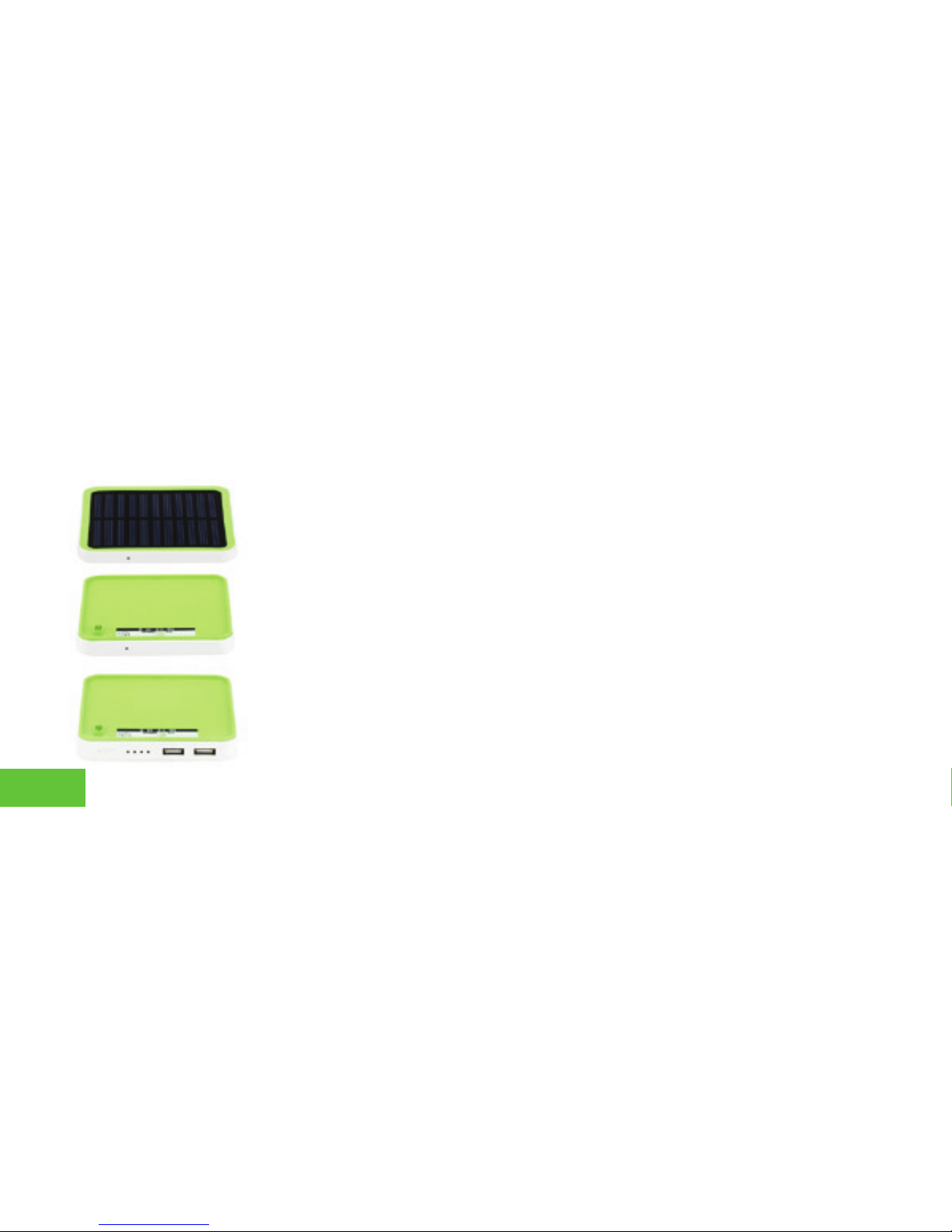
1. Main Power Module
2. Main Power Module
3. Solar Module
4. Wireless Module
5. Charge Base
6. AC/DC Adapter
7. Smart LED Lighting Connector
8. Smart LED Micro USB Cable
NOTE 1. Solar Module is included with Model ECS-PS12KS4. Wireless Module is
not included in this model.
NOTE 2. Wireless Module is included with Model ECS-PS12KW4. Solar Module
is not included in this model.
NOTE 3. Instruction manual is included with each STAK Power Station model.
NOTE 4. Power Stations do not include iPod, iPhone, iPad or any USB
configuredmobiledigitaldevice.
5

7
8
109
3
2
1
4 5
6
II. STAK POWER MODULE INDICATORS/FUNCTIONS
6

4. USB OUTPUT PORTS [2]
6. LED INDICATOR BUTTON
5. MAIN POWER MODULE INDICATOR
Both USB Ports support up to 2.1A output speeds. Power
iQ & Auto-Detect Technology sense and automatically
apply the proper power needed by iOS mobile platform
andotherUSBcongureddevices.
Indicates charging and in tandem with the 4 LED indicator
buttons to show amount of power that is available in the
Main Power & Sub-Power Modules.
1. MAIN POWER MODULE
Controls input, output, and auto-detects the power
volume of the Main Power Module and Sub-Power
Modules. Includes built-in 6000mAH (milliamp hours)
polymer battery.
2. MAIN POWER MODULE
Power expansion module. Includes built-in 6000 mAH
Lithium polymer battery.
3. SOLAR MODULE
Monocrystalline silicon matt solar module automatically
activated during ideal sunlight conditions to assist Main
Power & Sub-Power Modules in charging iOS module
platormandotherUSBcongureddevices.
75 - 100% 50 - 75% 25 - 50% 0 - 25%
7

10. SOLAR MODULE INDICATOR
8. PARALLEL CONTACTORS
7. INPUT PORT
Micro USB port used to charge Main Power Module .
Max power input: 5V/2A by connecting with Micro
USB included cable.
9. MAIN POWER MODULE INDICATOR
Conrmsthatthemodulesaresecurelyconnectedand
indicates power capacity.
Green indicates battery capacity is between
70 - 100%.
Blue indicates battery is between 40 - 70%.
Red indicates the battery capacity is between 5 - 40%.
Indicates the working status of the Solar Module.
Positive contact for connection and communication
between Main Power Module, and Solar Module.
Negative contact for connection and communication
between Main Power Module, Solar Module.
Communicating Now.
C
8

III. HOW TO STACK STAK POWER MODULES
1. StartbyplacingaMain PowerModule (4 LEDs + 2 USB ports) onafl
atsurfacewiththegreen side facing down and the Croonos brand facing
up. Take a Main Power Module (4 LEDs + 2 USB ports) and place it on top
of another Main Power Module.
2. Make sure to align the gold contacts on the top of the first Main
Power Module with the gold contacts on the bottom of the second Main
Power Module as shown in the illustration to the left.
3. AfterconfirmingproperalignmentofthegoldcontactsofeachMain
PowerModule,simplysnapfitthe2modulestogethersothattheyare
lockedintoplace.
4. If you require additional power capacity beyond the two (2) Main
Power Modules(6000mAh each), simply stack additional Main Power
Module on the bottom of the initial set of Main Power Modules. 9
IV. HOW TO STACK SOLAR/WIRELESS/ACCESSORYMODULES
1. Start by placing a Solar Module or Wireless Module, on top of a Main
Power Module as shown in the illustration to the left. Makesurethatthe
PowerModulesareflippedwiththegreensidefacingup.
2. Make sure that the 3 gold contacts on the bottom of the Solar or
Wireless Module and the 3 gold contacts on the Power Modules are aligned
as shown in the illustration to the left for a proper connection of STAK Power
Modules.
3. Once the 3 contacts on the bottom of the Solar Module or Wireless
Module are properly aligned with a Main Power Module,snapfitallofthe
modulestogethersothattheylockintoplace.
4. If you require additional power capacity beyond two (2) Main Power
Modules(6000mAh each), simply stack additional Main Power Modules to
the bottom of the stack.
10
This manual suits for next models
3
Table of contents


