CPS DPA03-800V/US User manual

Installation and Operation Manual
for CPS DPA03-800V/US AC Combiner
CHINT POWER SYSTEMS AMERICA CO., LTD.
Rev 2.0 Nov. 30, 2021

Table of Contents
2 / 27 Doc. No.: 9.0020.0589B0
Table of Contents
0Preface.....................................................................................4
1Safety.......................................................................................5
Symbols and meanings in this document..........................................5
Markings and meanings on the device..............................................5
Safety precautions of operating the Combiner ..................................6
2General Introduction..............................................................7
Overview of Grid-tied PV system.......................................................7
Appearance and dimension...............................................................7
Features of AC Combiner..................................................................8
Nameplate.........................................................................................9
2.4.1 Model No. .................................................................................9
2.4.2 Serial No.................................................................................10
Storage requirements......................................................................11
3Mechanical Installation........................................................12
Unpacking for Inspection.................................................................12
Installation requirements .................................................................12
3.2.1 Environment requirements......................................................12
3.2.2 Foundation requirements........................................................13
3.2.3 Installation requirements.........................................................13
Installation procedures ....................................................................13
Open and close the door.................................................................16
3.4.1 Open the door.........................................................................16
3.4.2 Close the door.........................................................................17
4Electrical Connection ..........................................................18
Electrical schematic diagram...........................................................18
Internal wiring terminals and cable specification .............................19
Recommended tools and torque values..........................................19
Wiring..............................................................................................20
4.4.1 Cable connection....................................................................20
4.4.2 Create conduit entry holes......................................................21
5Operation and Maintenance................................................22
Start up and shut down ...................................................................22
5.1.1 Start up ...................................................................................22
5.1.2 Shut down...............................................................................22
Maintenance....................................................................................23

Table of Contents
Doc. No.: 9.0020.0589B0 3 / 27
5.2.1 Regular inspection...................................................................23
5.2.2 Fuse replacement....................................................................23
6Technical Data ......................................................................24
7Quality Assurance................................................................25
Warranty period ...............................................................................25
Exemption of liability........................................................................25
Warranty clause...............................................................................25
8Contact Information.............................................................26
9Appendix...............................................................................27
Appendix A: Figure list.....................................................................27
Appendix B: Table list ......................................................................27

Preface
4 / 27 Doc. No.: 9.0020.0589B0
0 Preface
Thank you for choosing CPS DPA03-800V/US Series AC Combiner
(hereinafter referred to as "Combiner") developed by CHINT POWER
SYSTEMS AMERICA CO., LTD (hereinafter referred to as "CPS").
This Combiner is one highly reliable device, which is widely applicable in AC
combining of various PV systems.
IMPORTANT!
Please read this manual carefully and make sure that you have
understood all the contents thoroughly before you start any
operation.
Main Contents
Safety precautions, device overview, installation, operation and maintenance,
technical data as well as quality assurance are mainly introduced in this manual.
Target Reader
This manual is applicable to the work staff of wiring, installation, maintenance
and daily management of the Combiner.
Manual Management
Please store this manual together with related documents of other device
components, and make sure keep it at hand for quick reference and easy use.
Copyrights
CPS reserves all rights in this manual. Any reproduction, disclosure or copy in
whole or in part is forbidden without prior written authorization. CPS doesn’t
accept any responsibilities whatsoever for potential errors or possible lack of
information in this document.
Version
This manual is subject to technical change or contents modification without
prior notice. The actually purchased device shall prevail. Users can get the
latest manual from our sales channel or our official website:
www.chintpower.com.

Safety
Doc. No.: 9.0020.0589B0 5 / 27
1 Safety
Please read this user manual carefully before the installation and operation of this
Combiner. CPS reserves the right to refuse warranty claims for equipment
damages if users fail to install the equipment according to the instructions in this
manual.
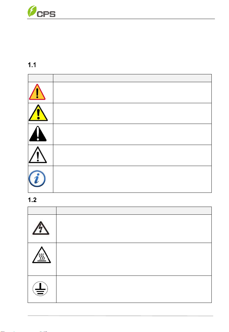
Symbols and meanings in this document
Markings and meanings on the device
Symbol
Meanings
HIGH VOLTAGE!
Danger to life due to high voltage!
All work on the device must only be performed by qualified
personal as described in this document.
HOT!
The equipment is designed according to international safety
standards, but surfaces can become hot during operation. DO
NOT touch the peripheral surfaces during or shortly after
operation.
EARTH GROUND!
This symbol marks the location of grounding terminal, which must
be securely connected to the earth through the PE (protective
earth) cable to ensure operational safety.
Symbol
Meanings
DANGER!
DANGER indicates a hazardous situation with highlevel of risk which,
if not avoided, will result in death or serious injury.
WARNING!
WARNING indicates a hazardous situation with medium level of risk
which, if not avoided, could result in death or serious injury.
CAUTION!
CAUTION indicates a hazardous situation with low level of risk which,
if not avoided, could result in minor or moderate injury.
NOTICE!
NOTICE indicates a hazardous situation which, if not avoided, could
result in equipment working abnormally or property loss.
IMPORTANT!
IMPORTANT indicates important supplementary information or
provides skills or tips that can be used to help you solve a problem or
save you time.

Safety
6 / 27 Doc. No.: 9.0020.0589B0
RoHS SYMBOL
In accordance with 2011/65/EU regulations, the inverter imposes
restrictions on the use of specific hazardous substances in
electrical and electronic equipment.
TUV Certification
This inverter has passed TUV Certification.
Safety precautions of operating the Combiner
Symbol
Meanings
DANGER!
Touching the wiring terminals inside the device may result in
death by electric shock!
DO NOT touch the terminals or conductors connected with PV
modules or PV inverters, which may result in death by electric
shock!
WARNING!
All the installation and wiring connections should be performed
only by qualified technical personnel.
Make sure both the AC and DC sources are disconnected, and
the shell of device is securely grounded to avoid electric shock
during maintenance or installation.
DO NOT touch live or exposed parts of the input and output sides
to avoid electric shock when checking or maintaining the device.
CAUTION!
Handle the Combiner carefully to prevent falling off due to its
weight!
Check the device and make sure there is no problem with the
installation before putting it into operation!
Connect the wires labeled L1/L2/L3/PE of the device to avoid
short circuit hazard, to ensure personal safety and the normal
operation of the device.
Although the Combiner is certified to international safety
standards, it will become hot during operation. DO NOT touch
the hot parts of the device during operation.
NOTICE!
Follow all the wiring and safety instructions of the Combiner.
All the wiring and operation must conform to the related local
standard requirements of the device.
IMPORTANT!
The device nameplate contains important information of the
device, such as model, serial number and detailed parameters.
If there is any problem or malfunction of the device during
operation, please contact our after-sales center and provide the
serial number. Our service personnel can provide timely service
for you.
Please keep the nameplate intact.

General Introduction
Doc. No.: 9.0020.0589B0 7 / 27
2 General Introduction
Overview of Grid-tied PV system
The Grid-tied PV system is generally made upof PV modules, string PV inverter
and AC Combiner, etc. The solar energy is converted by PV modules to DC
power and distributed to string PV inverter as the first level of current
combination, and then connected to AC Combiner for second level of current
combination. Now the AC power has the same frequency and phase with the
grid, which can be supplied in all or in part to local loads, with the remaining
power fed to the grid.
This AC Combiner shall be used in combination with the new generation of
CPS SCH275KTL-DO/US-800 series string PV inverter developed by CPS.
For the position and function of the AC Combiner in the Grid-tied PV system,
refer to Figure 2-1.
Figure 2-1 Grid-tied PV system
Appearance and dimension
Figure 2-2 Product Dimension

General Introduction
8 / 27 Doc. No.: 9.0020.0589B0
Figure 2-3 Product Appearance
Item No.
Component Name
1
Hasp locks (refer to Open the door)
2
Operation handle
3
Hooks
4
Handrails
Table 2-1 Component Name
Features of AC Combiner
High reliability
- High-voltage switch equipped with TYPE3R outdoor operation
handle, which is designed especially for PV system;
- Door cannot be opened once the machine is powered on;
- A transparent protection board made of PC material is installed
on front of the live components, protection function will be
triggered once the door is opened, to avoid your finger touch live
conductor.
Powerful protection performance
- Equipped with high-current, high-breaking and high-voltage AC
fuse.
- It is also possible to place a padlock on the disconnect switch for
Lockout/Tagout purposes.
Convenient installation and maintenance
- Be installed on mounting bracket;
- No locking screws are required.

General Introduction
Doc. No.: 9.0020.0589B0 9 / 27
Nameplate
The device nameplate contains important information of the device, including
model number, serial number and detailed parameters, etc.
You can find the nameplate of Combiner on the left side of its enclosure, as
shown in Figure 2-4.
Figure 2-4 Nameplate
2.4.1 Model No.
You can find out the model number of the Combiner on the nameplate, as
shown in figure 2-4. Each character included in the model has its special
meanings, as shown in Figure 2-5.
Figure 2-5 Naming convention of the model

General Introduction
10 / 27 Doc. No.: 9.0020.0589B0
2.4.2 Serial No.
The serial No. can be found out at the bottom left corner in the back side of the
door, as shown in Figure 2-6 (for reference).
Figure 2-6 Serial No.
The serial no is a list of 11 numbers and each number has its special meanings,
the bar code is made up of 128 codes, as shown below (just for reference).
Figure 2-7 Naming convention of the serial no.
IMPORTANT!
If there is any problem or malfunction of the device during operation
in the future, you can contact after-sales service center and provide
the device serial number.
Our service personnel can find out the date of production and other
necessary information quickly and provide service for you in time.
Therefore, please keep the nameplate complete and intact.
Table of contents
Other CPS Power Supply manuals