Control Module Genus User manual
Genus™ G1 Users Manual
Revision – 1-23-20 1
Genus™ WiFi Installation
Introduction
The 3046 WiFi Module provides wireless network connectivity or the CMI Genus™ series
terminals. The WiFi Module unctions as an Ethernet to Wireless LAN bridge and connects to
the Genus™ terminal’s RJ-45 Ethernet port. The WiFi Module will provide a seamless
connection to an 802.11b compliant Access Point (AP) that is within range. This WiFi Module
is compliant with the IEEE 802.11b standard and provides security and encryption unctions
or a secure and reliable network.
This document describes the Genus™ WiFi installation and setup. It also provides
troubleshooting in ormation and a Code 39 barcode table to assist in the setup o the Module
using a digital barcode wand. This provides easy access to special characters that are not
available on the Genus™ terminal keypad, but may be required or SSID, WEP Keys, and
other security parameters.
Please note that the WiFi Module may be re erred to as “Module” within this section o the
document.
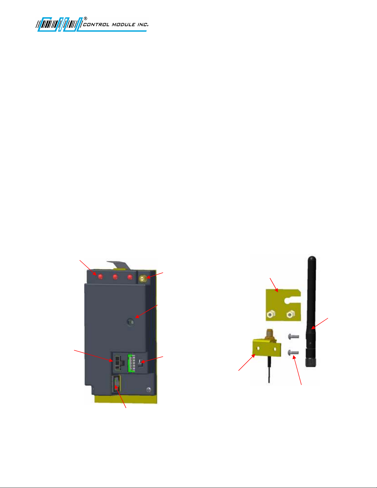
WiFi Module
Base Mounting
Bracket
Antenna
Antenna
Base
Mounting Screws
(Supplied)
Status LEDs
Comm, Link, Power
Antenna Cable
Connection
Power
LED
ON/OFF
Switch
Power
Port
RJ45 Connection to
G1 Terminal
Ethernet Cable
(Supplied)
Genus™ G1 Users Manual
Revision – 1-23-20 2
Hardware Installation
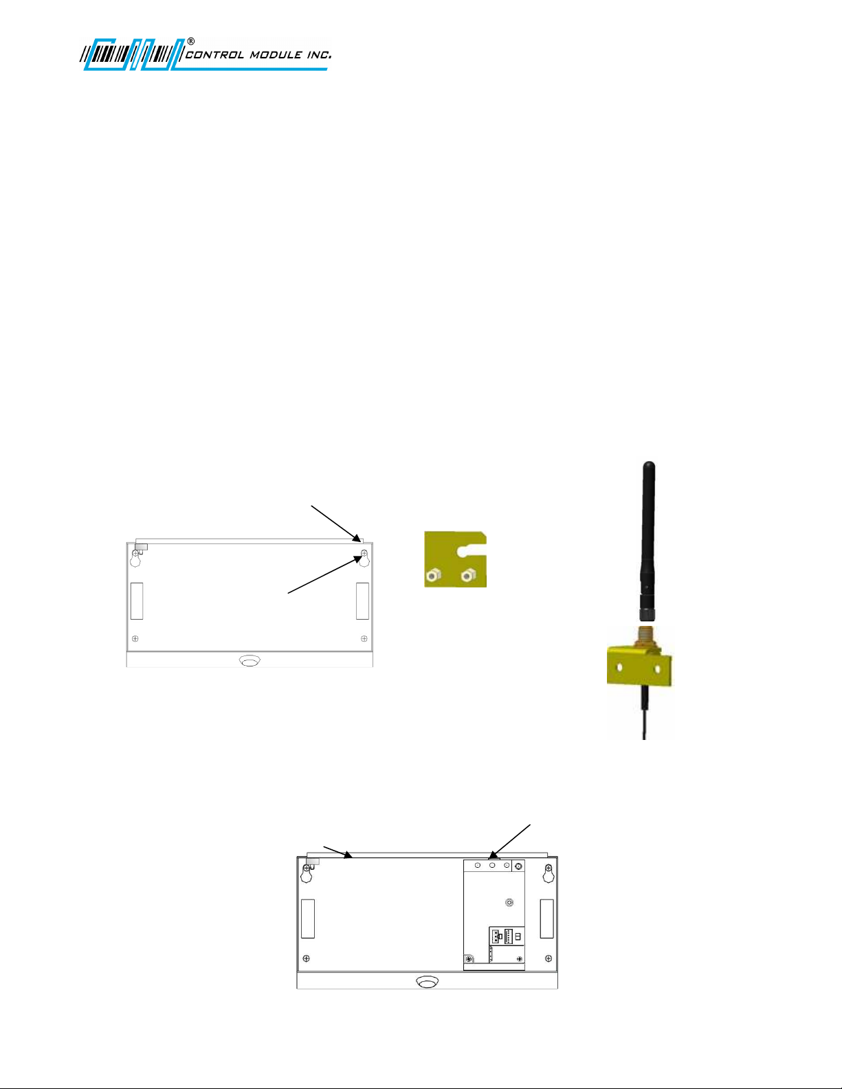
Antenna and bracket assembly to t e G1 Base
The antenna assembly is mounted directly to the G1 Base.
• Make sure the knockout or the antenna has been removed rom the base.
• Loosen the top right base screw to it this bracket.
• The Mounting Bracket (Figure 1) slides under the base screw at the top right
corner.
• Re-tighten the base mounting screw.
• The Antenna (Figure 2) can be tightened down to the Antenna Base (Figure 3).
Note: The Antenna Nut should be tightened enough so that when the antenna
is rotated the nut does not loosen.
• The Antenna portion o the assembly its through the knockout at the top o the
base.
• Two supplied screws secure the antenna assembly to the base mounting bracket.
Adding t e WiFi Module
• The 3046 WiFi Module has a spring tab that must make contact with the ground
bar inside the top o the base.
• Press the 3046 WiFi Module into the base until it snaps securely in place.
Figure 1
Base mounting Bracket
Figure 2
Antenna
Figure 3
Antenna Base
Antenna knockout
position - Top o base.
Loosen this
mounting screw.
Ground Bar
Spring Tab
Genus™ G1 Users Manual
Revision – 1-23-20 3
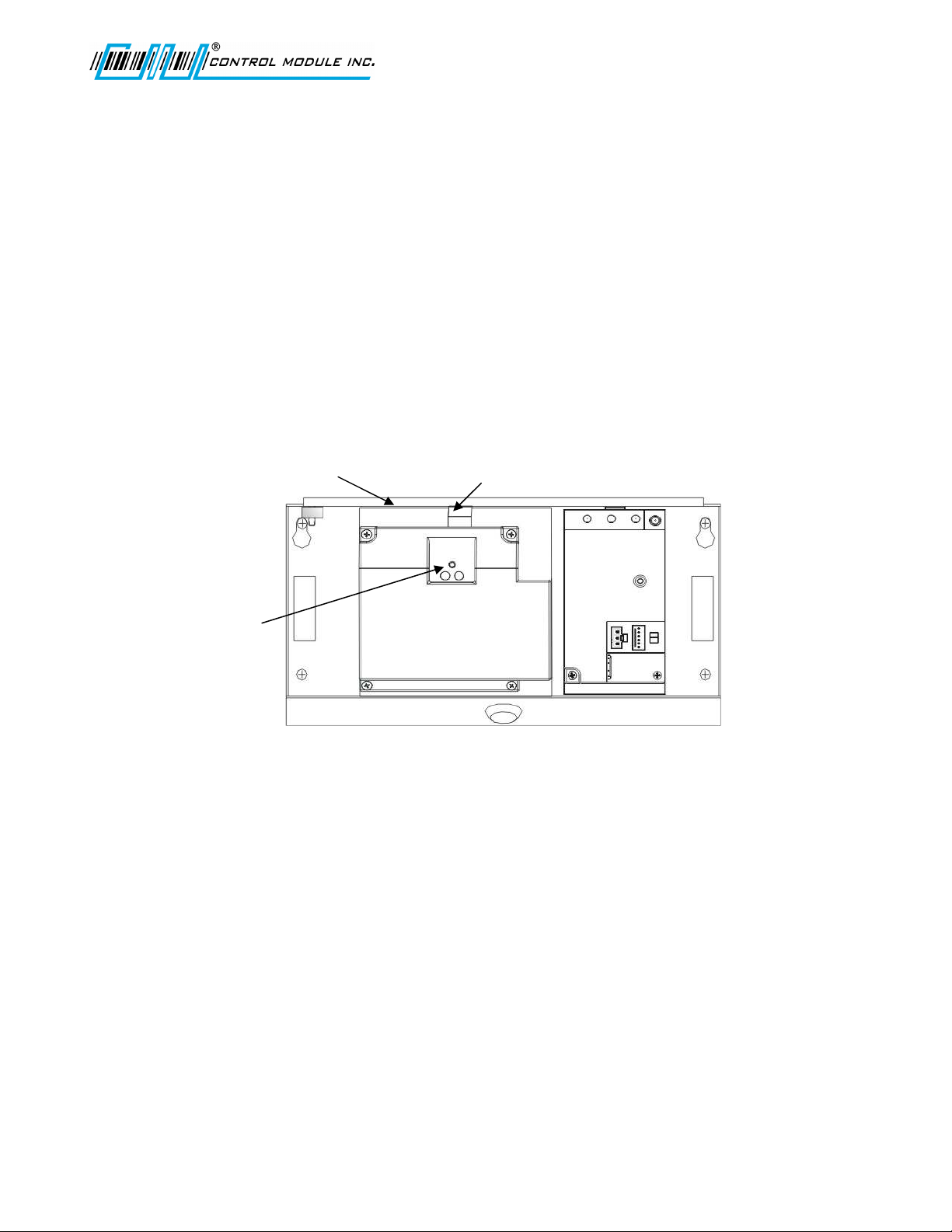
Adding t e UPS (Option)
• The 2050 UPS has a spring tab that must make contact with the ground bar inside
the top o the base.
• Press the 2050 UPS into the base to the le t o the WiFi Module until it snaps
securely in place.
• Momentarily depress the disconnect switch on the 2050 UPS, to ensure the battery
is disconnected. Should the yellow LED be lit the disconnect switch must be
pressed again.
Note: New Battery modules are shipped in the discharged mode and must be
powered to attain ull capacity, 1000 mAh require 20 hours to be ully charged.
WiFi Module
UPS
Ground Bar Spring Tab
Disconnect
Switch
Genus™ G1 Users Manual
Revision – 1-23-20 4
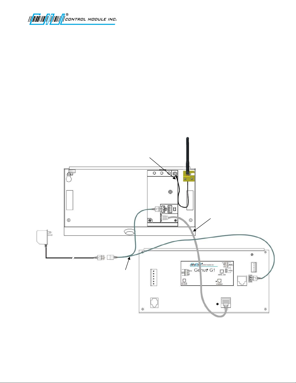
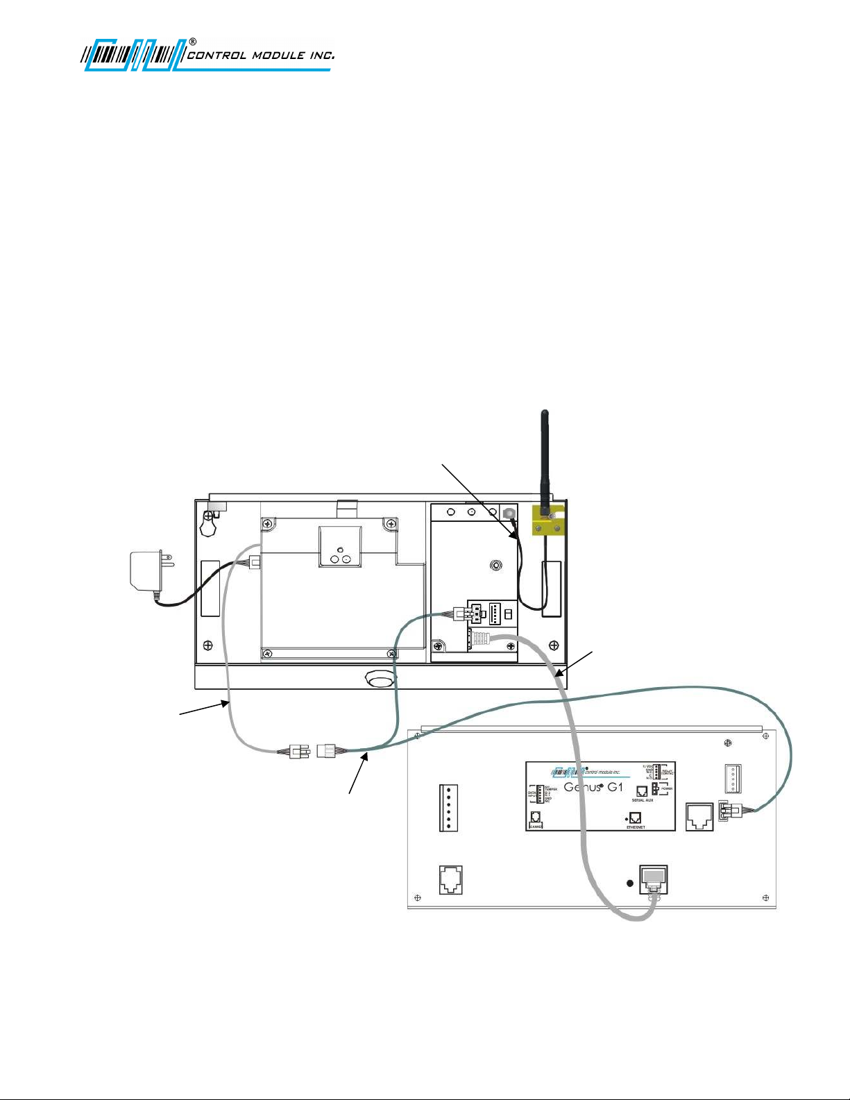
G1 WiFi Connections – Wit out UPS
• Ensure the WiFi Module power switch is o .
• Connect Antenna cable to WiFi Module, secure onto the Module.
• Connect Ethernet cable rom WiFi Module to the G1 Terminal, RJ45 connections.
• G1 Y-Cable connection or power.
o Connect the 3-position connector rom the power Module to the Y-Cable
o Connect one end o the Y-Cable to the WiFi Module and the other to the G1
Terminal.
Note: To make these connections, the Y-Cable and the Ethernet cable are
shipped with the WiFi Module.
• Ensure the WiFi Module power switch is on prior to Terminal power-up.
Y-Cable
Ethernet
Cable
Antenna
Cable
Genus™ G1 Users Manual
Revision – 1-23-20 5
G1 WiFi wit UPS Connections
• Ensure the WiFi Module power switch is o .
• Connect Antenna cable to WiFi Module, secure onto the Module
• Connect Ethernet cable rom WiFi Module to the G1 Terminal, RJ45 connections.
• Connect the power Module to the UPS.
• G1 Y-Cable connection or power.
o Ensure the UPS disconnect switch has been pressed.
o Connect one end o the Y-Cable to the WiFi Module and the other to the G1
Terminal.
o Connect the 2050 UPS cable to the Y-Cable.
• Ensure the WiFi Module power switch is on prior to Terminal power-up.
UPS
Cable
Antenna
Cable
Ethernet
Cable
Y-Cable
Table of contents


