Concept Perugini PTR Series User manual

INSTRUCTION BOOK
Manufactured by
CONCEPT PERUGINI S.R.L.
Via Dell’Artigianato, 11-15
47014 Meldola (FC)
Italia
TEL.: +39 0543494602
FAX: +39 0543 494727
www.conceptagri.com
CONCEPT PERUGINI S.R.L. RESERVES THE RIGHT TO MODIFY THEIR
PRODUCTS WITHOUT PRIOR NOTICE AND THE COMMITMENT TO UPDATE
THIS MANUAL
FLAIL MOWERS
CONCEPT PERUGINI S.R.L. RESERVES THE RIGHT TO MODIFY THEIR
PRODUCTS WITHOUT PRIOR NOTICE AND THE COMMITMENT TO UPDATE
THIS MANUAL
CONCEPT PERUGINI S.R.L. RESERVES THE RIGHT TO MODIFY THEIR
PRODUCTS WITHOUT PRIOR NOTICE AND THE COMMITMENT TO UPDATE
CONCEPT PERUGINI

INDEX
Introduction . . . . . . . . . . . . . . . . . . . . . . . . . . . . . . . . . . . . . . . . . 3
Instruction Manual. . . . . . . . . . . . . . . . . . . . . . . . . . . . . . . . . . . . 4
Identifi cation . . . . . . . . . . . . . . . . . . . . . . . . . . . . . . . . . . . . . . . . 5
Before operation . . . . . . . . . . . . . . . . . . . . . . . . . . . . . . . . . . . . . 5
Safety . . . . . . . . . . . . . . . . . . . . . . . . . . . . . . . . . . . . . . . . . . . . . . 5
Symbols . . . . . . . . . . . . . . . . . . . . . . . . . . . . . . . . . . . . . . . . . . . . 5
General Safety Instruction . . . . . . . . . . . . . . . . . . . . . . . . . . . . . 7
Operator’s Prerequisites. . . . . . . . . . . . . . . . . . . . . . . . . . . . . . . 7
Work Clothing . . . . . . . . . . . . . . . . . . . . . . . . . . . . . . . . . . . . . . . 7
Attaching the machine to the Tractor . . . . . . . . . . . . . . . . . . . . 8
ET Headstock. . . . . . . . . . . . . . . . . . . . . . . . . . . . . . . . . . . . . . . . 8
HT Front or Rear . . . . . . . . . . . . . . . . . . . . . . . . . . . . . . . . . . . . . 9
PTO Shaft . . . . . . . . . . . . . . . . . . . . . . . . . . . . . . . . . . . . . . . . . . 10
Working Depth. . . . . . . . . . . . . . . . . . . . . . . . . . . . . . . . . . . . . . 10
Side Shift . . . . . . . . . . . . . . . . . . . . . . . . . . . . . . . . . . . . . . . . . . 11
In the Field . . . . . . . . . . . . . . . . . . . . . . . . . . . . . . . . . . . . . . . . . 11
Road Transport . . . . . . . . . . . . . . . . . . . . . . . . . . . . . . . . . . . . . 11
Maintenance. . . . . . . . . . . . . . . . . . . . . . . . . . . . . . . . . . . . . . . . 12
Storage . . . . . . . . . . . . . . . . . . . . . . . . . . . . . . . . . . . . . . . . . . . . 15
Spare Parts. . . . . . . . . . . . . . . . . . . . . . . . . . . . . . . . . . . . . . . . . 15
Warranty . . . . . . . . . . . . . . . . . . . . . . . . . . . . . . . . . . . . . . . . . . . 16

3
Introduction
Concept Perugini S.R.L would like to thank you for purchasing this Flail mower
and off er their support and assistance throughout its productive life.
We strongly recommend that this booklet is read and understood before using
your new machine, and that regular maintenance is carried out as described
further in the booklet. If any doubts arise then don’t hesitate to contact your local
dealer or the company via the options provided on the front page or via Facebook
@ Concept Perugini.
We recommend you take a moment to write down the Serial Number, Year of
Manufacture and Model, as this information will facilitate ordering spare parts.
Serial Number:
Year of Manufacture:
Model:
your new machine, and that regular maintenance is carried out as described
further in the booklet. If any doubts arise then don’t hesitate to contact your local
dealer or the company via the options provided on the front page or via Facebook
@ Concept Perugini.
We recommend you take a moment to write down the Serial Number, Year of
Manufacture and Model, as this information will facilitate ordering spare parts.
Serial Number:
Year of Manufacture:

4
Instruction Manual
The aim of this manual is to help you (the user) understand how to use and how
to maintain the machinery. This booklet covers the following models : AT ET JT
HT PT TT
PT PTR
PT PTR
HT
ET
ET
AT
AT
JT
JT
HT
TT
TT

5
Identifi cation
The identifi cation plate, attached to the machine shows the following information:
• Manufacturer’s Name
• CE mark
• Year of production
• Serial number
• Recommended tractor horsepower
• Overall weight
• P.T.O. speed and direction of
rotation
These data are very important in order to check the compatibility between the
machine and the tractor and when ordering spare parts
Before operation
At the factory each machine is carefully inspected to guarantee proper
functioning. In addition, the dealer, before delivering the machine should have
carried out a pre delivery inspection. However as a precaution measure check:
• Oil level in the gearbox
• Grease all those components provided with grease nipples
• Air pressure in the tractor’s tyres, length of lift arms
• Tractor PTO speed to match the machine transmission speed
Safety
Symbols
In this booklet three diff erent symbols are used to highlight danger levels or
important information
DANGER
To draw the operator’s attention to situations which could
endanger his or other people safety.
CAUTION
To draw the operator’s attention to situations which could aff ect
the machine performances but not his or other people safety.
IMPORTANT
To draw the operator’s attention to situations which do not aff ect
the machine performances and his or other people safety.
It is important to comply with the instructions given by the safety stickers, which
must always be on the machine. If new ones are required, contact your dealer.

6
SYMBOL DESCRIPTION
1
Before operation, adjusting
or servicing the machine,
it is important that each
operator carefully reads the
following instructions.
Servicing lubrication etc.
should be carried out with
the engine stopped, the
brakes applied and locked
and the starter key removed.
2
Anybody who is near the
machine when working,
must keep at a safe
distance.
During operation keep away
from rotating parts and PTO
shaft. Do not remove safety
guards whilst the machine
is working or with engine
running.
3
Danger of injury to lower
body parts. Anybody who
is near the machine when
working must keep a safe
distance at all times.
4
Danger of injury to limbs.
Anybody who is near moving
parts must be aware of
where his body is in relation
to the machine and keep
at a safe distance. Do not
remove safety guards.
5
Any servicing should be
carried out with the tractor
off and the correct parking
procedures should be
followed out as advised by
the manufacturer. Should
the machine need to be
raised it should be supported
securely.

7
General Safety Instruction
• During operation keep away from rotating parts and PTO shaft, do not
remove safety guards during operation or with the engine running.
• Servicing should be carried out with the engine stopped, the brakes applied
and locked and the started key removed. Once the machine is raised do not
work underneath unless supported securely.
• When travelling on the public road disconnect the PTO shaft and carefully
follow the traffi c regulations of your country.
• Always lift the machine from the lifting points.
• The operator should be experienced and in good health in order to avoid
injury to his person and others.
• The operator must wear the correct safety garments.
• Do not work when dark unless suitable lighting is available
Operator’s Prerequisites
To avoid danger to himself and others, the operator must be:
• Physically sound
• Mentally sound
• Trained
We advise that the operator read and understand this booklet before using
the machinery. If there are any doubts then contact your dealer or CONCEPT
PERUGINI S.R.L
Work Clothing
The operator must wear the following:
• Working gloves
• Overalls of appropriate size
• Working boots
• Protective glasses
• Protective helmet
When lifting the machine always use the appropriate lifting gear
and always use the lifting points indicated by the yellow and black
stickers as shown in picture.

8
Attaching the machine to the Tractor
Concept Perugini Flail toppers can be linked up to any tractor with a category 1
or 2 three point linkage.
Read the tractor’s instruction manual before attaching attempting to attach the
machine to the tractor.
• Adjust the width of the tractor arms to match the lower brackets on the
machine
• On a fl at surface reverse the tractor up to the machine
• Firstly attach the lower links and do the necessary adjustments to limit
sideways movement
• Lengthen and attach the top link in order to have the machine parallel to the
ground once attached
• Remember to fi t all the locking pins and that the machine is safely secured
to the tractor
NB On the PT the top link bracket is provided with a hole and a slot to attach the
tractor’s top link. It is important that during transport the top link is secured via the
hole and during work the slot is used. Failing to follow these instructions could
result in serious damage to the headstock sliding mechanism and to injury.
ET Headstock
The ET comes with a fi xed headstock but has 2 options as to where to attach the
3 point tractor linkage, this is to off er a fi xed off set option. To attach the machine
to the tractor proceed as previously described but choose the desired brackets,
either to have the machine directly behind the tractor or off set.
If the ET is attached with in position
Athen the machine sits behind the
tractor as a normal fi xed fl ail mower.
If the machine is linked in position B
then the ET will be off set by 30 cm.
AB
ALWAYS MAKE SURE THE TRACTOR IS TURNED OFF, P.T.O
IS DISENGAGED AND MACHINE IS MADE SAFE
ALWAYS MAKE SURE THE TRACTOR IS TURNED OFF, P.T.O

9
HT Front or Rear
The HT is a versatile small fl ail mower, for tractors from 40 to 70 HP, it can be
mounted either on the rear as a standard fl ail mower or on the front as a front
mounted fl ail mower. When changing from rear mounted to front mounted
you need to remove the top link on the machine and place on rear side of the
headstock.
• Remove pins A
• Place machine top
link in position 2
and re-insert pins
into holes
A
POSITION 2
REAR
REAR
FRONT
FRONT
When transporting the HT it must be mounted on the tractor with both pins in the
top link. Whilst when in use pin Bmust be taken out, this allows the machine to
follow the course of the land.
•
•
REAR
FRONT
BB
REAR
FRONT
10
PTO Shaft
If necessary, cut the PTO shaft to the right length following the shaft
manufacturer instructions.
When attaching the PTO shaft to the machine and tractor make certain that if the
PTO shaft is fi tted with an overrun clutch this must be installed on the implement.
When connecting to the tractor verify that the locking pin is correctly located and
secure in place. Before use make sure all the chains and guards are correctly
fi tted.
The height of the machine from the ground is controlled by the rear roller, skids
and top link. Before using the fl ail mower make sure that the fl ails do not hit the
ground, this will result in extreme wear will damage the rotor.
Always adjust the top link to keep the machine parallel to the ground when
adjusting the height of the rear roller.
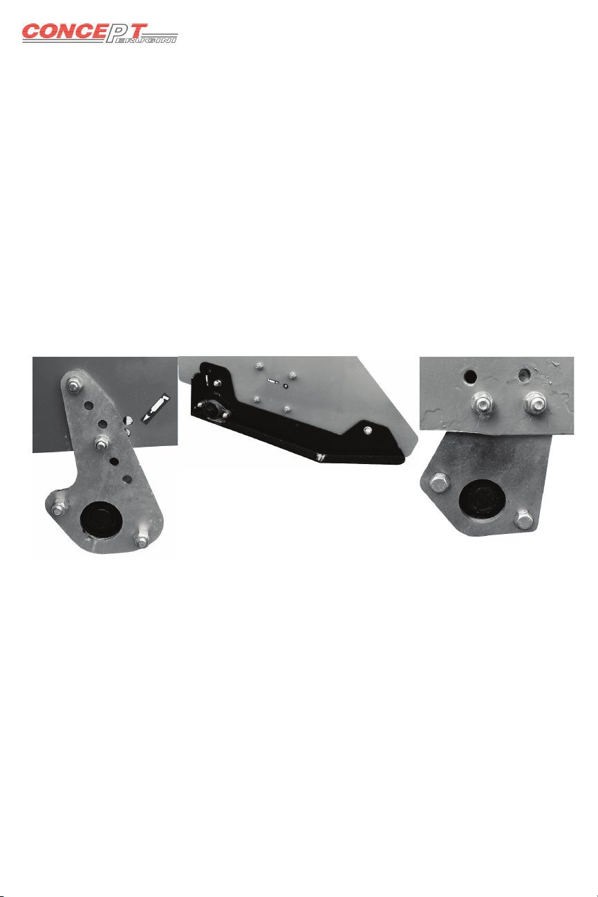
AT ET JT have the supports pictured in fi g.1 to alter the height of the roller
simply remove bolts A, position the plate so the holes align with either the higher
or lower holes on the plate and replace bolts A. On some of these models the
plates may be positioned on the inside of chassis. By moving the supports into
a horizontal position the roller can be moved further away from the fl ail rotor
allowing more space for rotor to discharge the cuttings.
TT model has the skids pictured in fi g.2 to alter simply remove bolt Band loosen
C, reposition the skid in the desired height and tighten B and C.
PT HT have the roller brackets shown in fi g.3. Undo bolts E move the plate to the
desired height and tighten bolts E. Depending on the width of the machine the
plates may be either on the inside of the chassis or the outside.
Working Depth
A
A
B
C
EE
1
2
3
This manual suits for next models
42
Table of contents
Other Concept Perugini Farm Equipment manuals


