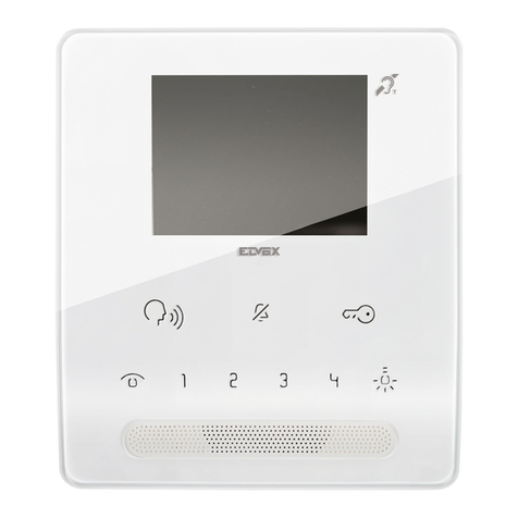
Commax CDV-71AM User manual

•Thank you for purchasing COMMAX products.
•Please carefully read this User’s Guide (in particular, precautions for safety) before using a product and follow
instructions to use a product exactly.
•The company is not responsible for any safety accidents caused by abnormal operation of the product.
•Thank you for purchasing COMMAXproducts.
•Please carefully read this User’s Guide (in particular, precautions for safety) before using a product and follow
instructions to use a product exactly.
•The company is not responsible for anysafety accidents caused byabnormaloperation of the product.
COLOR VIDEO DOOR PHONE CDV-71AM
User Manual

2
Table of Contents
Please follow the things described below in order to prevent any danger or
property damage.
Warning
Caution
Prohibition.
No disassembly
No touch
Must follow strictly.
Shows plugging out the power cord
without an exception
Shows the warning and caution for an electricshock.
Shows the warning and caution for a fire.
It may cause a serious damage or
injury if violated.
It may cause a minor damage or
injury if violated.
Please don’t disassemble,
repair or rebuild this product
arbitrarily (please contact the
service center if a repair is
needed.
·It may cause an electric
shock or fire.
When cleaning the product,
please rub it with a soft and
dry cloth after plugging out
the power cable. (Please don’t
use any chemical products
such as wax, benzene, alcohol
or cleanser.)
If an abnormal sound, burning
smell or smoke is coming out
of the product, please plug out
the power cable and contact a
service center.
·It may cause an electric
shock or fire.
Please don’t insert any
metallic or burnable materials
into the ventilation hole.
·It may cause an electric
shock or fire.
Cleaning & Use
Warning& Caution
1. Warning and caution
1. Warnings and Cautions...........................................................................2
Part Names. ............................................................................................3
Package Contents...................................................................................3
Wiring and Connection Instructions. .......................................................4
Installation...............................................................................................5
Operation......................................................................................................
5
7.
Specifications.........................................................................................15
2.
3.
4.
5.
6.

3
Power & Installation
Please don’t use several
products at the same time on
one power socket.
·It may cause a fire due to an
abnormal overheating.
Please don’t bend the power
cable excessively or it may
cause an electric shock.
·fire when using a damaged
power cable.
Please don’t handle the power
cable with a wet hand.
·It may cause an electric
shock.
Please plug out the power
cable from the socket when
not using it for a long period
of time.
·It may shorten the product
lifespan or cause a fire.
Please don’t install the
product in the place where
there is much oil, smoke or
humidity.
·It may cause an electric
shock or fire.
Please don’t install the
product with the lightening
and thunder.
·It may cause an electric
shock or fire.
Please don’t use and connect
this product with other
products with different rated
voltage
·It may cause a disorder or
fire.
When installing the product
that generates heat, please
install the product away from
the wall (10cm) for the
ventilation.
·It may cause a fire due to
the increased internal
temperature.
Warning& Caution
Parts Names
2.
3. Package Contents
Menu Button
Camera 1
Debug
Power Switch
Camera 2_use
Monitor Button
Interphone Button
Door Release Button
Talk Button
Volume Control Button
Speaker Microphone
On/Off & display LED
Priority talk menu button
Call Sound Control Button
CDV-71AM Wall Bracket Manual 2P Shunt
(Only NO.1 Cam.
if you insert 2P
T4X18
Wall bracket
mounting Screw
M3X8
Monitor
Fixing Screw Connector
4P(3EA) Connector
2P(3EA)
is available
shunt(short pin)
Camera Mode Select Button
NTSC/PAL select & reset
Camera 2
Interphone
CCTV 1
CCTV 2

1. RED : Image signal
CCTV Connector of polarity (2wires)
4. Wiring and Connection Instructions
1. Red: Talk (Audio)
2. Blue: GND
3. Yellow: Power (+12V)
4. White: Video
▷Polarity of the camera connector
1. Red: Talk (Audio)
2. Blue: GND
3. Yellow: Power (+14V)
4. White: Call signal
▷Polarity of interphone connector
●Please supply separate power to CCTV CAMERA.
●Please select coaxial cable depending on the distance of the camera.
VIDEO
GND
#①:RED-(VIDEO)
#②:Blue-(GND)
4
2. BLUE : GND
How to connect CCTV Camera

. Installation
5
Note
①Avoid the range of direct sunlight
②Recommended height is pertinent
from 1450 ~ 1500mm
③Avoid the installation near magnetic
activity, humid temperatures and gas
If you use UTP CABLE[CAT.5], connect
4 lines between monitor and interphone.
the rest 4 lines to GND after connecting
DOOR CAMERA & INTERPHONE Wiring
6. Operation
5
Each device should be connected by
If you use UTP CABLE[CAT.5] for
separated cables.
CAMERA1and CAMERA2, 2 lines of UTP
cable are required.
Monitor Camera
Monitor Interphone
UTP Cable
UTP Cable
※To display firmware version on the screen, press [▽] button
※To reset to PAL mode, press the [Select] button and [▽] button at the same time.
※To reset to NTSC mode, press the [Select] button and [△] button at the same time.
Note : When it is reset to PAL or NTSC, all saved data is deleted and language setting is
changed as English
Note : When install CCTV camera, video standard(PAL or NTSC) must be same with
installed door camera
Note : Only Camera 1 is available in factory default setting condition. In order to use
camera 2, jumper cap should be removed to activate no. 21 port.
※Volume control button: It is to adjust talking volume from counter side.
※Calling sound level control button: It is to adjust calling sound
※Screen resolution Button: Set the screen status at MENU -> GUI setting
※Usage of camera 2(refer to no. 21 on above drawing): In order to use 2nd camera,
jumper cap should be removed to activate no. 21 port.

●Receiving a calling from visitor
1. When the call button is pressed by a visitor at the door camera, the melody shall be
rung and visitors’ image is shown on the screen.
2. Press “talk” button( ) to talk with a visitor.
(Maximum 60 seconds is available to talk on the phone.)
3. Press “talk” button( ) again to close and return standby mode after finish the
talk.
4. Press “door release” button ( ) to open the door while on the conversation.
●Communication with a interphone
1. Press "talk" button ( ) and "interphone" button( ) in sequence to make a
conversation with the interphone connected with monitor.
(It is available to talk on the phone for Maximum 60 seconds)
2. When receiving a call from an interphone, electrical sound shall be rung.
Press “talk” button ( ) to start to talk.
3. When you receive a call from camera while talking with interphone, Visitor’s image
should be showed on the monitor.
It shall be possible to talk between each unit, monitor, interphone and camera.
Note : When you finish talking with visitor or interphone, press “talk” button again to
close the talk mode.
●Monitoring.
(This is sample case of being installed 2 door cameras & 2 CCTV cameras. If it is not
set like this, camera monitoring function shall not be deactivated.)
1. Press monitoring button ( ), appears camera image for 30 seconds.
2. Monitoring sequence (Screen will be changed by clicking the button in following
sequence below)
1) Camera 1 + CCTV1 (PIP mode)
a. Case 1: In case of no CCTV1 signal, screen will be switched to Camera 2 in
full screen mode.
2) Camera1 (Full screen)
3) CCTV1 (Full screen)
a. In case of no CCTV1 signal, screen will be switched to Camera 4(camera
2+CCTV)
How to operate
4) Camera 2 + CCTV2 (PIP mode)
a. Case1 : In case of jumper pin is set at “CA2_USE”like picture no. 21, screen
will be switched to Standby mode.
b. Case 2 : Incase of no CCTV2 signal, screen will be switched to camera5 in full
screen mode.
5) Camera 2 (Full screen mode)---In case of camera2 & removed jumper pin like
picture no.21
6

●Priority talk( )
When there is impeding noise that disturbs conversation from the door camera,
pressing and holding the “PTT” button will deliver only the voice of the speaker from
the CDV-71AM to the door camera unit to help clarify speech.
●Recording visitors image
※Recording visitors’ image. (Not apply to CCTV) Manual recording Press and hold
the “monitoring” button (REC) for 1 second under “ talk” or “ monitoring” mode to
save a cut of image with electric sound .Auto recording In auto recording mode, a
cut of image is saved every time a visitor push the call button.
(Talk function is available by pressing talk button( ) after finishing auto
recording)
●Function of icons
display camera 1
display camera 2
display CCTV 1
display CCTV 2
6) CCTV2 (Full screen mode)
a. In case of no CCTV2 signal, switched to standby mode
(In case of jumper pin is set at “CA2_USE”, CAM2 & CCTV2 are not activated.)
●PIP location settings function
1) This function enables users to set the location of PIP display on the screen.
2) PIP function is activated only when both a door camera and a CCTV camera are
connected to the device.
- During monitoring or talking with a visitor through a door camera, use the “DOWN
BUTTON” as shown below to move the location of PIP in clockwise direction.
7

Down Button
●GUI functions
Press the “Menu” button, then the screen will be displayed like below.
Press the button beside each arrow to execute
Touch menu is not support in this menu.
Display save images
Setup menu
Time setting menu
Display setting menu
Language setting menu
Save setting menu
the function.
8

●Review recorded images
Press the “Menu” button, then the screen display like below.
Buttons to turn 4 pages at a time
Button to select desirable screen
Button to switch to full-screen mode
: Next screen : Previous screen
: Delete current screen
(Image will be deleted after verifying pop-up menu)
Switch screen to previous menu.
(Press the “MEMU” button to move back to main screen
: Quad-screen view mode
9

●Setup
Setting menu : system configuration menu
Time setting menu
Display setting menu(Brightness, Contrast, Color)
Language setting.(Korean, English, Russian, Spanish, Persian, Turkish, Polish)
Save menu setting: Auto save, manual save, delete all saved images
Move to previous menu
10
Other manuals for CDV-71AM
1
Table of contents
Other Commax Intercom System manuals

Commax
Commax DRC-4BH User manual

Commax
Commax DRC-4BH User manual

Commax
Commax DRC-40K User manual

Commax
Commax TP-12RM User manual
Commax
Commax CMP-2BCS User manual

Commax
Commax DRC-481L Operating manual

Commax
Commax DR-24ML User manual

Commax
Commax DRC-4CPN2 User manual

Commax
Commax CDV-70UM User manual

Commax
Commax DPV-4MTN User manual

Commax
Commax DRC-GUM/RF1 User manual

Commax
Commax DR-nUM User manual

Commax
Commax CMV-70S User manual

Commax
Commax DRC-nAC2 User manual

Commax
Commax Fine View CDV-35HM User manual

Commax
Commax CMP-2BAS User manual

Commax
Commax WDP-180D User manual

Commax
Commax DRC-GAC User manual

Commax
Commax CDV-50 User manual

Commax
Commax DRC-40DK User manual