CNC-Step High-Z Series Operating and maintenance instructions

Status: 30.05.2017
Quick Start Guide
High-Z Series
https://www.cnc-step.de/en/

Quick Start Guide
High-Z Series
CNC-STEP e.K. ▪Siemensstrasse 13-15 ▪ 47608 Geldern ▪ Germany
Page 2
Support: +49 (0)2831/91021-50
27.09.2013
High-Z Series
Short Description
This Quick Start Guide will help you with the initial start-up of the machine.
It also includes optional accessory that is connected directly to the machine or control.
For more detailed information please refer to the individual manuals.

Quick Start Guide
High-Z Series
CNC-STEP e.K. ▪Siemensstrasse 13-15 ▪ 47608 Geldern ▪ Germany
Page 3
Support: +49 (0)2831/91021-50
27.09.2013
CONTENTS
1CONNECTORS AND CABLES ON THE MACHINE.....................................................5
2CONNECTIONS TO OF THE ZERO-3 STEPPER MOTOR CONTROLLER................6
2.1 Front side ..................................................................................................................................6
2.2 Back side....................................................................................................................................7
3CONNECTING THE MACHINE TO THE ZERO-3 CONTROL......................................8
4CONNECTION POSSIBILITY OF A 4TH AXIS.............................................................9
5CONNECTION OPTIONS OF OPTIONAL ACCESSORIES.......................................10
5.1 Overview Connection and power supply via Zero-3 control..............................................10
5.2 Milling motors ........................................................................................................................11
5.3 Noga spray cooling with solenoid valve................................................................................11
5.4 Inverter and HF spindles.......................................................................................................12
5.5 Granitograv and laser engraving unit..................................................................................12
6SOFTWARE INSTALLATION.....................................................................................13
6.1 KinetiC-NC.............................................................................................................................13
6.1.1 CncPod...............................................................................................................................13
6.1.2 Connecting Hardware........................................................................................................14
6.2 WinPCNC ...............................................................................................................................15
6.2.1 Installation.........................................................................................................................16
6.2.2 Connecting the computer to the Zero-3 control.................................................................16
6.2.3 Configuration.....................................................................................................................17
6.2.4 Determination of the LPT interface (Light and Economy) ...............................................17
6.2.5 Determination of the COM interface (Professional) .........................................................19
6.2.6 Entry of the determined interface / port address in WinPCNC.........................................20
6.2.7 Entry LPT2 port (only Economy)......................................................................................20
6.2.8 check the efficiency...........................................................................................................21
6.3 ConstruCam 3D......................................................................................................................22
6.3.1 Installation.........................................................................................................................22
6.3.2 Milling program generation with KinetiC-NC..................................................................22
6.3.3 Interaction with WinPC-NC..............................................................................................23
6.4 Other Software .......................................................................................................................23

Quick Start Guide
High-Z Series
CNC-STEP e.K. ▪Siemensstrasse 13-15 ▪ 47608 Geldern ▪ Germany
Page 4
Support: +49 (0)2831/91021-50
27.09.2013
7CUSTOMER SERVICE ...............................................................................................24

Quick Start Guide
High-Z Series
CNC-STEP e.K. ▪Siemensstrasse 13-15 ▪ 47608 Geldern ▪ Germany
Page 5
Support: +49 (0)2831/91021-50
27.09.2013
1Connectors and cables on the machine
The connecting leads are directly connected to the stepper motor controller Zero-3.
Caution: Before connecting the cables, please turn off the Zero-3 control !!!
D-Sub 9pol. X1
Motor connection cable X1-axis
D-Sub 9pol. X2
Motor connection cable X2 axis
D-Sub 9pol. Y
Motor connection cable Y-axis
D-Sub 9pol. Z
Motor connection cable Z-axis
D-Sub 9pol. ST
Control line ST
Lug
Ground Connection
The miniXLR jack provides the option of connecting extensions without additional hardware.
For example:
Tool length control, Security housings with door switch
3D Buttons
Note:
Concomitant use of this socket and a 4th axis, such as a rotation axis or tangential knife, the
connectivity is limited because both the miniXLR socket and the reference switch the 4th axis are
found via the PIN15 of the LPT port.
For this combination, we have a solution. To do so, please contact our customer service.
Mini-XLR-jack

Quick Start Guide
High-Z Series
CNC-STEP e.K. ▪Siemensstrasse 13-15 ▪ 47608 Geldern ▪ Germany
Page 6
Support: +49 (0)2831/91021-50
27.09.2013
2Connections to of the Zero-3 stepper motor cont roller
2.1 Front side
7 8
1 2 3 4 5 6 9
Front side Overview
1Connector D-Sub 9pol. for motor X1
2Connector D-Sub 9pol. for motor X2
3Connector D-Sub 9pol. for motor Y
4Connector D-Sub 9pol. for motor Z
5Connector D-Sub 15pol. for 4th axis (Rotary axis / tangential knife)
6Connector D-Sub 9pol. for Control line ST
7Emergency-stop-button
8Power-button
9Status-LEDs
Zero-3 Front Side

Quick Start Guide
High-Z Series
CNC-STEP e.K. ▪Siemensstrasse 13-15 ▪ 47608 Geldern ▪ Germany
Page 7
Support: +49 (0)2831/91021-50
27.09.2013
2.2 Back side
5 6
1 2 3 4 7
Overview back side
1 power supply (115-240V input voltage)
2 LPT1 input
3 LPT2 input
4 LPT2 output (0-10Volt Edition)
5 Socket 1 (115-240V depending on input voltage - switchable via relay 1)
6 Socket 2 (115-240V depending on input voltage - switched via relay 2)
7 Ground (High-Z series > 03/2015)
Note on the sockets 1 + 2:
The two sockets are with two relays switchable. Thus, the consumer connected to it can be switched
on and off via software.
This guarantees also that the power supply is interrupted at faults and in emergency case.
The maximum power consumption per outlet may not exceed 8A.
The current consumption of the two sockets together may not exceed 13.5A.
Zero-3 Back Side

Quick Start Guide
High-Z Series
CNC-STEP e.K. ▪Siemensstrasse 13-15 ▪ 47608 Geldern ▪ Germany
Page 8
Support: +49 (0)2831/91021-50
27.09.2013
3Connecting the machine to the Zero-3 control
- Make sure that the control is turned off.
- Connect all 5 cables with the Zero-3 controller.
- Make sure that you back up all connections with the knurled screws from loosening.
Zero-3 Front Side
Connection cable of the machine

Quick Start Guide
High-Z Series
CNC-STEP e.K. ▪Siemensstrasse 13-15 ▪ 47608 Geldern ▪ Germany
Page 9
Support: +49 (0)2831/91021-50
27.09.2013
4Connection possibility of a 4th axis
On the C-terminal of the zero-3 control another step motor can be operated as the fourth axis. In
addition to this port, a 12-24V supply for an oscillation motor and the connection for a further
reference switch are supplied.
- Make sure that the control is turned off.
- Connect the supplied power cable to the C-socket of the controller.
- Make sure that you back up all connections with the knurled screws from loosening.
Zero-3 Front Side
Rotation Axis
TCM-3
EOT-2
TCT-1
Quick Start Guide
High-Z Series
CNC-STEP e.K. ▪Siemensstrasse 13-15 ▪ 47608 Geldern ▪ Germany
Page 10
Support: +49 (0)2831/91021-50
27.09.2013
Compressor
5Connection options of optional accessories
The accessories at this point we just cover briefly the connection to the machine to the controller
and if necessary to the additional hardware interface (depending on the software).
For more detailed information please refer to the individual manuals.
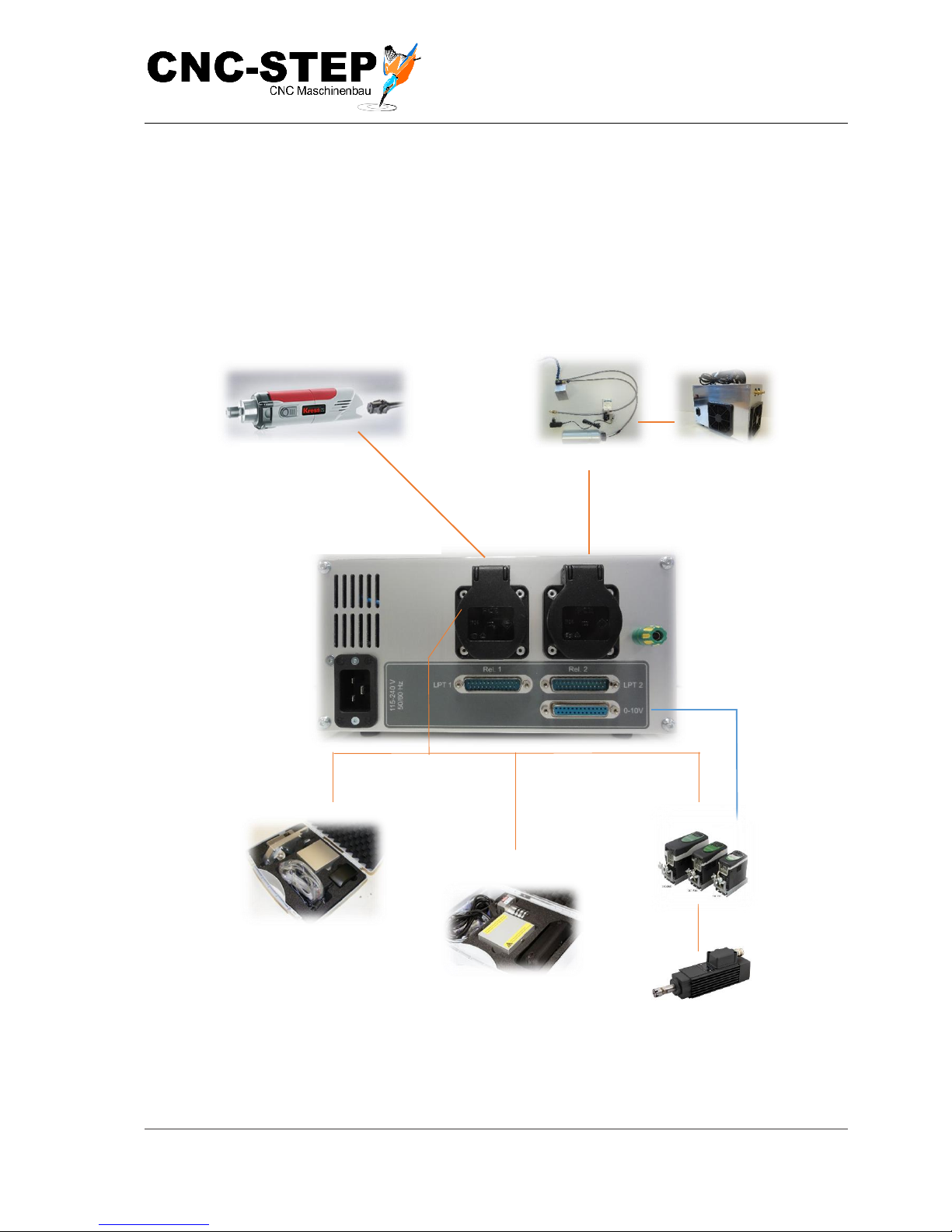
5.1 Overview Connection and power supply via Zero-3 control
Milling motors
Noga spray cooling
Control signals
Zero-3 Back Side
Granitograv
Laser engraving unit
Converter / HF-spindle
This manual suits for next models
1
Table of contents


