UK Instruction Sheet Template – V1.1 – Updated: 20/11/2020
The CLP Ultrablade Pro Surface Mount LED Exit is a surface mount fitting. It can be attached directly to
any solid surface. Please follow the steps below to install the CUBPRO-SM Exit:
•Open the fitting using the 2 screws on either side of the blade.
•Locate the mounting surface.
•Drill holes in the mounting base to suit the mounting method, Ceiling or Wall (see images below).
•Use the mounting bracket to mark-out the mounting holes for Ceiling or Wall Mount.
•Drill power access hole as required.
•Mount the fitting using appropriate fixings.
•Route the power to the mains connection and connect the 240VAC supply.
•Attach the blade assembly to the bracket and tighten the 2 mounting screws.
•Apply power to the fitting and test.
•This luminaire contains non-user replaceable light source and battery.
•If the CTP capabilities are activated, please affix the CTP Status Label to a visible surface and add
F to marking label to show AFG.
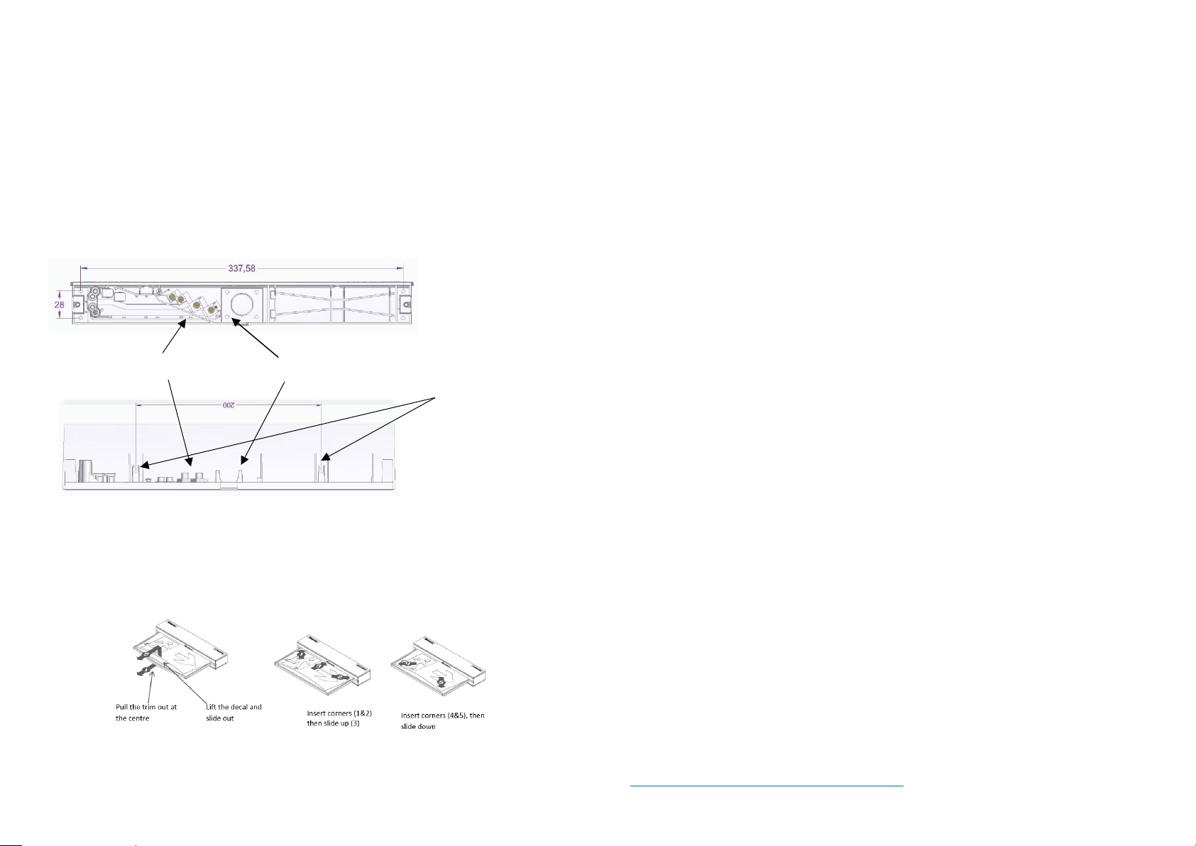
Changing EXIT Legend Inserts
:
The Ultrablade Pro Exit comes with an assortment of standard legends.
1. To remove the legend, grasp the centre of the bottom trim piece and pull down slightly to expose the legend
edge. See photo.
2. Grasp the bottom edge of the legend and slide the existing legend out of the blade, while working the edges
out along the sides.
3. Slide the new legend into the blade, ensuring to fit the edges into the sides then slide the legend to the top
of the blade. Insert one bottom corner then the other. Slide the legend down into the bottom trim.
Note:
This luminaire (with reinforced insulation between control/LED terminal and AC supply) contains non-user
replaceable light source and battery - to be replaced (if required, refer installation instructions for battery
replacement) by Clevertronics service personnel/agents or a registered electrician.
1. Prior to any work, isolate the power to the luminaire that requires battery replacement
2. Open the fitting using the 2 screws on either side of the blade and slide out fitting.
3. Remove the Battery Connector from the Emergency Driver.
4. Remove the battery.
5. Replace battery, securing into battery compartment, and connect to Emergency Driver.
6. Refit fitting and secure the 2 screws on either side.
1. Prior to any work, isolate the power to the luminaire that requires battery replacement
2. Open the fitting using the 2 screws on either side of the blade and slide out fitting.
3. Remove the Battery Connector from the Emergency Driver.
4. Remove the screw holding the driver PCA. Remove the PCA.
5. Remove the 4 screws holding the battery bracket. Remove the bracket with the battery.
6. Disconnect the signal cable from LED strip.
7. Remove 4 self-tapping screws and unclip the LED strip.
8. Install the new LED strip following the above procedure in reverse.
When the unit is connected to the un-switched active, it must be allowed to charge the battery for at
least 24 hours. Conduct the following tests:
•The emergency lamp must illuminate for at least 180 min after disconnection from the mains. If the
unit fails to illuminate for the requisite time, remedial action must be taken to repair the situation
and once completed, the unit must pass a subsequent test.
•Press and hold Test Button or switch Off Mains Supply, check that the emergency lamp is On.
•Release the Test Button or Switch ON Mains Supply, check that the emergency lamp is Off (Non-
maintained operation).
Below are a list of common problems and their possible causes.
Fault: The Green LED Test Switch indicator is not illuminated.
Check: A.C. is connected and is turned on.
Battery is connected
Test Switch for damage.
Fault: Lamp does not illuminate in emergency mode.
Check: A.C. is connected.
Lamp is correctly inserted.
Battery is connected
Fault: Lamp illuminates in emergency mode, but only stays on for a short period.
Check: Battery has been allowed to charge for at least 24 hours.
Caution:
On many building sites, power circuits may be cut off in an uncontrolled and repetitive basis during
construction. As a result, any Exit & Emergency Units, on these circuits, will have their batteries
discharged or “cycled”. The Li-ion battery in the luminaire has been selected to give excellent long life
performance in a controlled IEC 60598-2-22 testing environment. Excessive battery cycling will reduce
through-life performance and may lead to premature battery failure. Battery warranty claims, as a result
of such abuse, are specifically EXCLUDED from Clevertronics warranty terms.
Warranty:
For Product Warranty information and Terms and Conditions of Sales please refer to our website
https://clevertronics.co.uk/product-warranty-statement/
Ceiling Mounting Points (4)
Power Connections Power Access


