
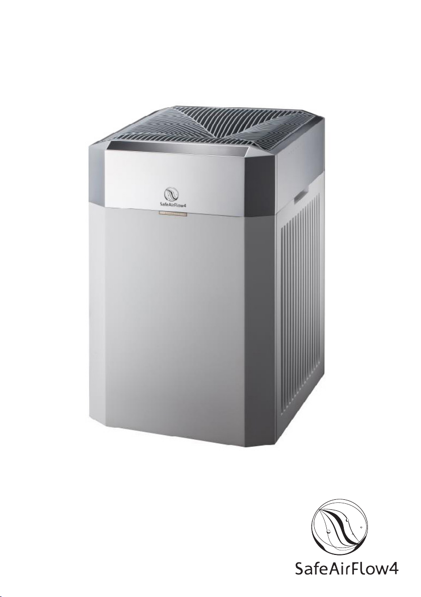
Clear Safe Product SafeAirFlow4 User manual
1
ENGLISH
User’s Manual
www.SafeAirFlow.com

2

3
Contents
1 Product Structure
Product structure display
Display instructions
2 Product Functions and Features
3 Main Performance Parameters
4 Application and Scope
5 Attentions
6 Installation Method
7 Placement Instructions
8 Usage
Start machine
Air volume touch control
9 Maintenance
Clean primary lter
Clean top grill
Clean and maintain sensor
10 Replace lter element
11 FAQ and Troubleshooting
2
2
3
3
4
4
5
6
7
8
8
8
8
8
9
9
10
10

4
1. Product Structure
The equipment adopts the principle of circular wind ultraviolet disinfection to
achieve sustainable disinfection and sterilization of indoor air.
It’s designed for special environments such as all levels of hospitals, outpatient
operating rooms, ICUs, protective isolation wards, treatment rooms, dispensing rooms,
etc. It can be used in Class II, III and IV medical environments.
The product can sterilize instantly under the condition of coexistence of man
and machine, reducing the risk of nosocomial infection and improving the level
of sensory control.
SafeAirFlow4 elements
Primary lter
Filter element cover
UV-C lter element
Sensor cover
Top grill

5
2. Product Functions and Features
Disinfection eect after a 24 hrs period:
The killing rate of Staphylococcus albicans is ≥99.9 %
The killing rate of natural bacteria is ≥90 %
The killing rate of viruses is ≥99.99 %.
SafeAirFlow4 structure display
WiFi connection status
(Only applicable to WiFi model 2022)
Mode switch button
UV LED indicator
Air volume display
Display the remaining time of
the lter element at the end
of its service life.
Air quality indicator
Air quality respectively corresponds
to green, yellow, orange and red.
Green : excellent air quality
Yellow : good air quality
Orange : average air quality
Red : poor air quality
Operating mode
AUTO: automatic mode
For improving indoor air quality, fan
speed is adjusted according to PM2.5
dust content which is detected by laser
sensor automatically.
ECO: Energy saving mode
Operate at the status of low energy
consumption and low noise.
Power button
PM2.5 Value

6
3. Main Performance Parameters
Normal working conditions:
Temperature range : 5-40 °C,
Humidity : ≤85 %,
Power supply : AC 220 V
4. Application and Scope
The product can be used in Class II, III and IV medical environment.
Such as waiting rooms, treatment rooms, patient rooms etc
SafeAirFlow4
390 x 420 x 630 mm
about 15 kg
120 W
4x 24 Watt UV-C PHILIPS PL-L
50 Hz
2400 m3(depening on contamination level)
≤68 dB(A)
Mobile, free of installation
Model
Size L x W x H
Net weight
Input power (W)
Lamps
Rated frequency
Applicable space
Noise
Installation

7
5. Attentions
Please read the manual carefully before use.
Please keep the manual after reading.
1. Please place the machine in a safe place where it is not easily to be kicked down.
2. Please turn o power and remove the plug from the socket, when the machine is
not used for a long time. If you need to turn o power, make sure to pull out the
plug part, and do not directly pull the power cord out.
3. Do not continue to use, when the machine is broken or damaged due to other
reasons, or the product operation fails. Do not place the power cord near or on a
hot surface.
4. Please close the doors and windows during the machine operation.
5. Do not use the machine until it is properly installed.
6. Do not use the machine in the environment of ammable or explosive gas.
7. Do not leave the machine in the rain, or use it near water, such as laundry
or other wet places.
8. The machine must be placed vertically for use.
9. Do not allow foreign matters to enter the air inlet or air outlet to avoid electric
shock, re or damage to the machine. Do not cover the machine.
10. Place the machine close to the power outlet, and avoid using extension cable.
11. If the plug and socket are loose, it may cause overheating or plug distortion.
Please contact a qualied electrician to replace the loose or damaged socket.
12. If the power cord is damaged, it must be replaced by the manufacturer, other
service oce or qualied personnel to avoid danger. Do not continue to use. Do
not sit, stand or place heavy objects on the machine.
13. Disconnect the power before repairing.

8
6. Installation Method
The product uses modular lter element design,
and all replacement methods are shown below.
a. Take the lter element out of the package
c. Press down the two xing clips, and then
pull the primary lter screen toward you to
remove it.
b. Open the cover of lter element, pull
the buckle toward you, and take it o.
d. Install the lter element as the direction
indicated on it. Connect the reserved power
cable of the lter element chamber to the
UV module.
Please note that the power cord has voltage 220 V,
do not connect the machine power before connecting!
1
2

20 cm
10 cm
20 cm
9
7. Placement Instructions
Placement Location, Choose the right place.
Recommend to close the doors and
windows for the best purication eect.
e. After the installation of lter element,
put the primary lter screen back.
Repeat the above
steps to install
the lter element on
the other side.
f. Put the cover of lter element back.
In order to get better performance,
the air inlet should be kept at certain
distance from the walls and other
obstructions during using.
Make sure that the side with the two xing clips is facing
to you and that all hooks of the primary lter screen are
properly connected to the machine.
1
1
2
2

10
8. Usage
9. Maintenance
Make sure the machine is plugged into an electrical outlet.
Start machine
Air volume touch control
Clean primary lter
a. Press the power button.
The primary screen helps to block the larger airborne
particles absorbed. The primary lter screen can be taken
out and cleaned by hand in warm water. Pay attention to
clean gently.
After the primary lter screen is completely dried, it can be
installed back into the machine.
Recommende to clean it every month.
b. Press the mode switch button.
The machine enters AUTO
operation mode.
Switch between AUTO
and ECO mode.
Air volume adjustment
The machine enters AUTO
operation mode.
Do not carry out maintenance operation until
the main engine stops running and power is o.
Table of contents


