CLEAN ROOM DEVICES CRD610 User manual

1
CRD610 Automatic Fitting Inserter
OPERATIONS MANUAL
ORIGINAL INSTRUCTIONS
VERSION 1.6
LAST EDITED 06.27.2019
cleanroomdevices.com

2
Table of Contents
Title Page………………………………………………………………….……1
Table of Contents………………………………………………………………..2
1.0 General Product & Safety Information………….…………………………3
1.1 Product Information
1.2 Safety Information
1.3 Lifting and Moving Safety
2.0 Installation/Setup………………………………………………………….5
2.1 Fitting Inserter Electrical
2.2 Fitting Inserter Air Supply
2.3 Pin Set Installation
2.4 Jaw Set Installation
2.5 Adjusting the Stop Gate
2.6 Magazine Installation
2.7 Adjusting Last Fitting Sensor
3.0 Operation……………………………………………………………….….13
3.1 Loading Magazine and Jaws
3.2 Fitting Sensor Lamp
4.0 Maintenance………………………………………………………………..14
4.1 Daily
4.2 Every Three Months
5.0 Recommended Spare Parts…………………………………………………14
6.0 Product Specifications……………………………………………………..14
7.0 Trouble Shooting…………….………………………………………….….15
8.0 Durometer Scale……………………………………………………………15
9.0 Electrical & Pneumatic Diagrams……………………………..….………..16
10.0 Alcohol Dispenser Option…………………………………………….…..18
11.0 Parts List……………………………………………………………….….23
12.0 Warranty………………………………………………………….………..26
12.1 Warranty
12.2 Warranty Period

3
1.0 General Product & Safety Information

4
Figure 1
1.1 Product Information
The Fitting Inserter is designed to hold and locate soft tubing while inserting a fitting into
the tubing.
The minimum/maximum outside tube diameter is 1/4” to 3/4”
1.2 Safety Information
This product uses air cylinders and electronic sensors to pneumatically actuate the closing
jaws. The unit is not intended for anything other than flexible tubing.
CRD610 AUTOMATIC FITTING INSERTER SAFETY NOTICE
PLEASE READ CAREFULLY BEFORE CONTINUING
Warning
The fitting inserter should only be operated by trained, qualified
personnel who have read and understand this manual.
The owner of this CRD610 is responsible for training all personnel to properly
operate this unit. Failure to follow instructions may result in serious personal
injury.
Never, under any circumstances operate the “Automatic Fitting Inserter” with
the cover or guarding removed or any safety device disabled.
1.3 Lifting & Moving Safety
Due to the weight of the unit (approximately 44 lbs/20 kg), the unit should always be
moved or repositioned by two (2) people to reduce the possibility of injury. (Figure 2)

5
Figure 2: Always Team Lift for Safety
2.0 Installation/Setup
Ensure all five (5) rubber feet are completely stabilized on your work surface prior to applying
air pressure and electrical power to the unit.
100.75 Electrical Supply
Plug the electrical connector into the back of the fitting inserter and plug the 24VDC
power supply into a 110V outlet (220V for European power supplies). The smart
relay inside the machine may have as much as an eight (8) second power up
time before the fitting inserter becomes fully operational.

6
Figure 2.2.1
1. 24 VDC Power Supply Jack
2. Compressed Air Supply, use 1/4” tubing
3. Air Supply to Alcohol Dispenser, use 5/32” tubing
4. Return from Alcohol Dispenser, use 5/32” tubing
2.2 Air Supply
Connect a 1/4” air supply hose to the fitting found on the back of the Automatic Fitting
Inserter. The air supply should be free of moisture and contaminates and supplies 100-
120 psi. It is important to have the ability to shut off the air pressure or disconnect
from the main air line. A quick-connect coupling or ball valve is recommended.
Figure 2.1.1
The air supply will need to be off or disconnected when manually cycling the pin set
actuation air cylinder.
Safety Note: Keep hands clear of moving parts when connecting or disconnecting the air supply.
The jaws may move suddenly. Failure to do so may result in serious injury.
Ensure that the High Pressure Regulator is set between 80-120 psi. (shown in Figure
2.2) The unit must have a minimum of 80 psi to operate properly.
Ensure that the Low Pressure Regulator is set between 20-40 psi. The Low Pressure
Regulator must always be set between 20-40 psi for the machine to function properly.
Caution: Do not set above 40 psi, as high pressure can cause premature wear to
the machine and/or damage the unit.
1
2
3
4

7
Figure 2.2.2
1. Power On/Off Switch
2. Alcohol Dispenser On/Off Switch
3. Alcohol Primer On/Off Switch
4. Low Pressure, Regulator/Gauge
5. High Pressure, Regulator/Gauge
6. Magazine
7. Operational Counter with reset
8. Fitting Sensor

8
2.3Pin Set Installation
NOTE: AIR SUPPLY MUST BE DISCONNECTED AND THE JAWS MUST BE IN
THE CLOSED POSTION.
Remove the magazine from the unit by pulling straight up. Loosen the six button head
screws on both sides of the cover. Lift the cover up and carefully place on left side of
base as wire and air lines are connected from the cover to the unit.
The CRD610 is equipped with a Pin Set Assembly which is designed for a specific tube
fitting.
Before installing the pin set, roll the pin on a flat surface to insure that it is straight.
Insert the pin tip into the hole near the bottom of the magazine rack. Slide the pin
through the hole until it is horizontal within the CRD610. Figure 2.4.6
Push the pin toward the back of the unit until the threaded end reaches the threaded
cylinder rod. Turn the pin clockwise to tighten.
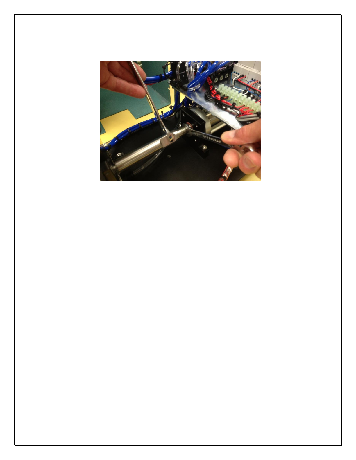
Once the pin is hand-tightened, pull the pin forward exposing the cylinder. Figure 2.4.7
Place a 1/2” open end wrench on the flats of the cylinder rod and hold in place.
Place a 5/8” open end wrench onto the flats of the pin set and tighten pin set into the
cylinder rod. Figure 2.4.8
Manually pull the pin forward to ensure it goes through the magazine and into the jaw
set.
9
Figure 2.4.6 Figure 2.4.7
Aligning the pin Threading pin to cylinder
Figure 2.4.8
Tightening pin to cylinder
2.4 Jaw Set Installation (Air supply must be disconnected)
With the cover off, loosen the four 5mm screws holding the jaws into the block
Remove the jaws and replace with new set.
Retighten the four 5mm screws.
Check the pin-jaw alignment for pin concentricity. With the air turned off and the
magazine in, place a piece of tubing in the jaw set and clamp the tubing manually with
the jaws. Pull the pin forward manually through the magazine and ensure that it lines up
with the center of the inner diameter of the tubing. Gently rotate the pin to ensure that
there is no wobble in the pin head.
Failure to do so may result in severe damage to both the magazine and jaw set!
If any wobble is detected, recheck that the threads on the cylinder and pin set are clean.
If there is still a wobble, the Pin Set Assembly is bad and another must be used.
2.5 Adjusting the Stop Gate

10
The distance between the end of the jaw set and the stop gate may need to be adjusted
according to what fitting is being used. This distance to adjust the stop gate is
determined by the gap between the fitting flange and the end of the tubing. Sliding the
stop gate away from the front of the unit will insert the fitting deeper into the tubing.
Figures 6 and 7 below show the tubing before adjusting the stop gate and after
adjusting the stop gate:
Figure 6 Figure 7
Unadjusted Stop Gate Adjusted Stop Gate
To adjust this distance, loosen the one 5mm socket cap screw on the side of the gate
and move the gate in or out depending on the stick out desired (figures 8 and 9 below).
Re-tighten the screw before attempting to run the unit.
Figure 8 –Loosening the socket head cap screw Figure 9 –Sliding the gate forward
If the fitting is not being fully inserted, adjust the gate backwards, towards the pin. If
the fitting is being pushed on too far, or the tubing is rolling, adjust the gate forward,
toward the operator. Verify that the tip of the pin set is well centered with the jaw set
in both a left-to-right view point and an up-and-down view point.
Table of contents
Popular Industrial Electrical manuals by other brands

Rexroth Indramat
Rexroth Indramat DURADRIVE SYSTEM200 Project planning manual

Abtech
Abtech HVJB Series Installation, operation & maintenance instructions

Murata
Murata GRM0335C1H8R1DA01 Series Reference sheet

SAF-HOLLAND
SAF-HOLLAND CBX 5415.5 Installation and operation manual

Eaton
Eaton Ulusoy HMH24-04 user manual

Newlong
Newlong NP-7H NSTRUCTION MANUAL/PARTS LIST

Murata
Murata GJM0335C1E4R4BB01 Series Reference sheet

Stahl
Stahl 8575/12 operating instructions

SI
SI Pegasus installation instructions

Murata
Murata GRM1555C1H2R7CA01 Seies Reference sheet

Murata
Murata GRM0225C1E6R4BA03 Series Reference sheet

Cooper Power Systems
Cooper Power Systems VXE15 Installation and operation instructions


