Cisco MERAKI MR36H User manual

MR36H Installation Guide
The Cisco Meraki MR36H is a dual-band 802.11ax cloud-managed access point with integrated Ethernet ports. Designed for room wireless and wired
connectivity, the MR36H is easy to install on the wall on a single gang box, and is the first cloud managed hospitality AP.
About this Guide
This guide provides instructions on how to install and configure your MR36H access points. This guide also provides mounting instructions and limited
troubleshooting procedures. For more wireless installation guides, refer to the wireless installation guides section on our documentation website.
Product Overview
Physical Specifications
MR36H
Interfaces
• 1x Gigabit Ethernet (RJ45) with 802.3af Power over Ethernet output *
• 2x Gigabit Ethernet (RJ45) outputs
• 1 to 1 Passthrough port
*it can work with 802.3af with lower capabilities
Power
• Power over Ethernet: 37 - 57 (802.3at compatible)
• Power consumption: 25W max (802.3at)
• Power over Ethernet injector sold separately
Environment
1

• Operating temperature: 32 °F to 104 °F (0 °C to 40 °C)
• Storage and Transportation Temperature: -4 °F to 158 °F (-20 °C to 70 °C)
• Humidity: 5 to 95% non-condensing
Physical Security
• Two security screw options (included)
• Concealed mount plate
Package Contents
The MR36H package contains the following:
MR36H Cloud-Managed Access Point
Mount cradle
2

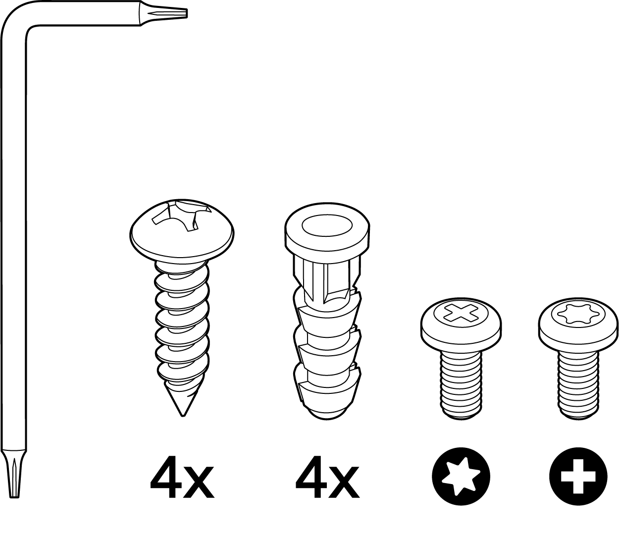
Mount Kit
3

Eject/Security Screw Tool, Wall Screws (Phillips), Wall Screw Anchors, Torx Security Screw, Phillips Security
Screw
Mounting Compatibility
MR36H fits perfectly on the MA-MNT-MR-H2A and MA-MNT-MR-H3A.
If retrofitting mount of MR30H to MR36H is necessary, meaning the old mounting brackets will be used for MR36H, or the mounting plate included with the
MR30H (MA-MNT-MR-H1A) which is directly mounted to an electrical box would be used, then there is a two to four screws to be removed and replaced.
The difference between the included mount plates for the MR30H (MA-MNT-MR-H1A) and the MR36H, is that the passthrough cutout is twice as wide because
MR36H needs both ports on the back to be used.
The same mounting plate that fits MR30H could be used If the use of the MR36H's passthrough port is not needed, as that is the part that will be covered by the
old bracket.
Security Features
The MR36H features multiple options for physically securing the access point after installation:
1. Security screw – The accessory kit includes screws that can be used to secure the access point to the mount cradle. Engaging the security screw
prevents accidental dislodging and theft.
4

Ethernet Ports
Uplink
The MR36H features a Gigabit Ethernet RJ45 port that accepts 802.3at and 802.3af power on the rear of the unit. This port should be used for uplink to your
WAN connection.
LAN Access Ports
The MR36H features 3x LAN ports labeled 1 through 3. Port 1 may provide 802.3af out to an end device if the MR36H is powered via a 802.3at power source.
Configuration details can be found in the AP port profiles article.
5

The LAN ports on an MR36H behave like access ports on a switch, and will not accept incoming traffic if it has a VLAN (802.1q) tag applied.
Connecting another MR to the LAN ports of the MR36H is not a supported topology.
Through MR-4072 we learnt that if another MR is connected to the LAN port of an MR36H, DHCP requests from that MR will not be forwarded from the LAN
ports, this is designed as such to prevent erroneous mesh topologies from forming.
Power Source Options
The MR36H access point can be powered via PoE using either the Meraki PoE Injector (sold separately), or a PoE switch.
The MR36H will function in low power mode when powered by a 802.3af power source. While in low power mode, the MR36H will disable 802.3af out on the
LAN1 port. Despite being in low power mode, the device can still supply full wireless capabilities.
6

Factory Reset Button
If the button is pressed and held for at least five seconds and then released, the MR36H will reboot and be restored to its original factory settings by deleting all
configuration information stored on the unit.
The factory reset button is located on the rear of the unit and must be ejected from the mount plate in order to be activated.
LED Indicators
7

A - System Status LED
B - Ethernet status LEDs
System Status
The MR36H is equipped with a multi-color LED light on the front of the unit on the top right to convey information about system functionality and performance.
The LED shines through the faceplate of the AP and is not visible when either disabled via Run Dark mode or powered off.
•Orange - AP is booting (permanent Orange suggests hardware issue)
•Blinking Orange - AP can't find uplink
•Rainbow - AP is initializing/scanning
•Blue - AP in Gateway mode with clients
•Blinking Blue - AP is upgrading
•Green - AP in Gateway mode with no clients
8

Ethernet Status
The MR36H features four green Ethernet status LEDs near the bottom of the faceplate. When an Ethernet client is connected, the LED will shine through the
faceplate if Run Dark mode is not enabled.
Run Dark Mode
The MR36H may be operated in “Run Dark” mode for additional security and to reduce the visibility of the access point. In this mode, the LED will not be
illuminated. This mode may be configured through the Meraki dashboard.
When a MR36H is rebooted with rundark mode enabled, an orange LED will illuminate during boot then all lights will be turned off after boot.
Safety and Warnings
These operations are to be taken with respect to all local laws. Please take the following into consideration for safe operation:
•Power off the unit before you begin. Read the installation instructions before connecting the system to the power source.
•Before you work on any equipment, be aware of the hazards involved with electrical circuitry and be familiar with standard practices for preventing
accidents.
•Read the wall-mounting instructions carefully before beginning installation. Failure to use the correct hardware or to follow the correct procedures could
result in a hazardous situation to people and damage to the system.
•This product relies on the building’s installation for short-circuit (overcurrent) protection. Ensure that the protective device is rated not greater than: 15 A,
125 Vac, or 10A, 240 Vac.
•Please only power the device with the provided power cables or standard PoE to ensure regulatory compliance.
Pre-Install Preparation
You should complete the following steps before going on-site to perform an installation.
Configure Your Network in Dashboard
The following is a brief overview only of the steps required to add an MR36H to your network. For detailed instructions about creating, configuring and managing
Meraki wireless networks, refer to the online documentation (documentation.meraki.com).
1. Login to http://dashboard.meraki.com. If this is your first time, create a new account.
2. Find the network to which you plan to add your APs or create a new network.
3. Add your APs to your network. You will need your Meraki order number (found on your invoice) or the serial number of each AP, which looks like Qxxx-
9

xxxx-xxxx, and is found on the bottom of the unit. You will also need your Enterprise license key, which you should have received via email.
4. Go to the map / floor plan view and place each AP on the map by clicking and dragging it to the location where you plan to mount it.
Check and Set Firmware
To ensure your MR36H performs optimally immediately following installation, it is recommended that you facilitate a firmware upgrade prior to mounting your
MR36H.
1. Attach your MR36H to power and a wired Internet connection. See the "Power the MR36H" section for details.
2. The MR36H will turn on and the LED will glow solid orange. If the unit does not require a firmware upgrade, the LED will turn either green (no clients
associated) or blue (clients associated) within thirty seconds.
* If the unit requires an upgrade, the LED will begin blinking orange until the upgrade is complete, at which point the LED will turn solid green or blue. You should
allow at least a few minutes for the firmware upgrade to complete, depending on the speed of your internet connection.
Check and Configure Upstream Firewall Settings
If a firewall is in place, it must allow outgoing connections on particular ports to particular IP addresses. Check the Meraki Dashboard under the help section for
Firewall information.
Assigning an IP Address to the MR36H
All gateway MR36Hs (MR36Hs with Ethernet connections to the LAN) must be assigned routable IP addresses. These IP addresses can be dynamically
assigned via DHCP or statically assigned.
Dynamic Assignment
When using DHCP, the DHCP server should be configured to assign a static IP address for each MAC address belonging to a Meraki AP. Other features of the
wireless network, such as 802.1X authentication, may rely on the property that the APs have static IP addresses.
Static Assignment
Static IPs are assigned using the local web server on each AP. The following procedure describes how to set the static IP:
1. Using a client machine (e.g., a laptop), connect to the AP wirelessly (by associating to any SSID broadcast by the AP) or over a wired connection.
2. If using a wired connection, connect the client machine to the MR36H either through a PoE switch or a PoE Injector. If using a PoE switch, plug an
Ethernet cable into the MR36H’s Ethernet jack, and the other end into a PoE switch. Then connect the client machine over Ethernet cable to the PoE
switch. If using a PoE Injector, connect the MR36H to the “PoE” port of the Injector, and the client machine to the “LAN” port.
3. Using a web browser on the client machine, access the AP’s built-in web server by browsing to http://my.meraki.com. Alternatively, browse to
http://10.128.128.128.
4. Click on the “Uplink Configuration” tab. Log in. The default login is the serial number (e.g. Qxxx-xxxx-xxxx), with no password (e.g., Q2DD-551C-ZYW3).
10
Table of contents
Other Cisco MERAKI Wireless Access Point manuals

Cisco MERAKI
Cisco MERAKI MR44-HW User manual

Cisco MERAKI
Cisco MERAKI MR45 User manual

Cisco MERAKI
Cisco MERAKI MR56 User manual

Cisco MERAKI
Cisco MERAKI MR18 Manual

Cisco MERAKI
Cisco MERAKI MR30H User manual

Cisco MERAKI
Cisco MERAKI MR33 User manual

Cisco MERAKI
Cisco MERAKI MR44 User manual

Cisco MERAKI
Cisco MERAKI CW9166I User manual

Cisco MERAKI
Cisco MERAKI MR46E User manual

Cisco MERAKI
Cisco MERAKI MR36 User manual


 installation guide")
