Cervis SmaRT DIN-9H4R-2DI User manual
©2020 Cervis, Inc.
SmaRT DIN-9H4R-2DI Base Unit
User Manual
U127.0.0
™

SmaRT DIN-9H4R-2DI
FCC Statements
15.19 –Two Part Warning
This device complies with Part 15 of the FCC rules. Operation is subject to the following two conditions:
(1) This device may not cause harmful interference and
(2) This device must accept any interference received, including interference that may cause undesired operation.
15.21 –Unauthorized Modification
NOTICE: The manufacturer is not responsible for any unauthorized modifications to this equipment made by the user. Such modifications could
void the user’s authority to operate the equipment.
15.105(b) –Note:
Note: This equipment has been tested and found to comply with the limits for a Class B digital device, pursuant to part 15 of the FCC Rules.
These limits are designed to provide reasonable protection against harmful interference in a residential installation. The equipment generates,
uses and can radiate radio frequency energy and, if not installed and used in accordance with the instructions, may cause harmful interference to
radio communications. However, there is no guarantee that interference will not occur in a particular installation. If this equipment does cause
harmful interference to radio or television reception, which can be determined by turning the equipment off and on, the user is encouraged to try
to correct the interference by one or more of the following measures:
•Reorient or relocate the receiving antenna.
•Increase the separation between the equipment and receiver.
•Connect the equipment into an outlet on a circuit different from that to which the receiver is connected.
•Consult the dealer or an experienced radio/TV technician for help.
Industry Canada Statement
This device complies with Industry Canada licence-exempt RSS standard(s). Operation is subject to the following two conditions: (1) this device may not cause
interference, and (2) this device must accept any interference, including interference that may cause undesired operation of the device.
Le présent appareil est conforme aux CNR d'Industrie Canada applicables aux appareils radio exempts de licence. Le fonctionnement est soumis aux deux
conditions suivantes : (1) cet appareil ne doit pas causer d'interférences, et (2) cet appareil doit accepter toute interférence, y compris les interférences
susceptibles de causer un fonctionnement non désiré de l'appareil.
Industry Canada Statement
This device complies with Canadian RSS-210.
The installer of this radio equipment must ensure that the antenna is located or pointed such that it does not emit RF field in excess of Health Canada limits for
the general population; consult Safety Code 6, obtainable from Health Canada’s website https://www.canada.ca/en/health-canada/services/environmental-
workplace-health/reports-publications/radiation/safety-code-6-health-canada-radiofrequency-exposure-guidelines-environmental-workplace-health-health-
canada.html.
Le présent appareil est conforme à la norme CNR-210 d'Industrie Canada.
L'installateur de cet équipement radio doit s'assurer que l'antenne est située ou orientée de façon à ne pas émettre un champ RF dépassant les limites de
Santé Canada pour la population générale; consulter le Code de sécurité 6, disponible sur le site Web de Santé Canada https://www.canada.ca/en/health-
canada/services/environmental-workplace-health/reports-publications/radiation/safety-code-6-health-canada-radiofrequency-exposure-guidelines-
environmental-workplace-health-health-canada.html.
IC Unlicensed Devices EIRP Statements for Removable Antennas
Part 1: Under Industry Canada regulations, this radio transmitter may only operate using an antenna of a type and maximum (or lesser) gain approved for the
transmitter by Industry Canada. To reduce potential radio interference to other users, the antenna type and its gain should be so chosen that the equivalent
isotropically radiated power (EIRP) is not more than that necessary for successful communication.
Partie 1 : Conformément à la réglementation d’Industrie Canada, cet émetteur radio ne peut fonctionner qu'avec une antenne dont le type et le gain maximal
(ou inférieur) sont approuvés pour l'émetteur par Industrie Canada. Pour réduire les interférences radioélectriques potentielles avec d'autres utilisateurs, le
type d'antenne et son gain doivent être choisis de telle sorte que la puissance isotrope rayonnée équivalente (p.i.r.e.) ne soit pas supérieure à celle
nécessaire pour une communication réussie.
Part 2: This radio transmitter (LOBSRF-305) has been approved by Industry Canada to operate with the antenna type listed below with the maximum
permissible gain and required antenna impedance for each antenna type indicated. Antenna types not included in this list, having a gain greater than the
maximum gain indicated for that type, are strictly prohibited for use with this device.
Partie 2 : Cet émetteur radio (LOBSRF-305) a été approuvé par Industrie Canada pour fonctionner avec le type d'antenne indiqué ci-dessous avec le gain
maximal admissible et l'impédance d'antenne requise pour chaque type d'antenne indiqué. Il est strictement interdit d'utiliser avec cet appareil un type
d'antenne ne figurant pas dans cette liste ou ayant un gain supérieur au gain maximum indiqué pour ce type.
This document is the property of Cervis, Inc. and cannot be copied, modified, e-mailed, or reproduced
without the express prior written consent of Cervis, Inc.
Cervis, Inc. reserves the right to change this manual or edit, delete, or modify any information without prior
notification.

Base Unit Manual
©2020 Cervis, Inc.
i
Table of Contents
FCC Statements ........................................................................................................................... ii
Table of Contents.......................................................................................................................... i
List of Figures ............................................................................................................................... i
List of Tables................................................................................................................................. i
Cervis, Inc. Safety Precautions .................................................................................................. 1
1.0 SmaRT DIN-9H4R-2DI Base Unit......................................................................................... 2
2.0 SmaRT DIN-9H4R-2DI Installation ...................................................................................... 4
2.1 DIN-9H4R-2DI Base Unit Mounting Dimensions............................................................ 4
2.2 External Antenna Mounting............................................................................................. 5
2.3 SmaRT DIN-9H4R-2DI Terminal Connections................................................................ 6
3.0 SmaRT Handheld Remote to DIN-9H4R-2DI...................................................................... 7
4.0 SmaRT DIN-9H4R-2DI Variations........................................................................................ 7
5.0 DIN-9H4R-2DI Antenna and Cable...................................................................................... 7
6.0 SmaRT DIN-9H4R-2DI Specifications................................................................................. 8
Appendix A: Exposure to Radio Frequency Energy ................................................................ 9
Appendix B: Agency Identification Label Location.................................................................. 9
Appendix C: Typical Handheld to Base Unit Communication............................................... 10
C1: DIN-9H4R-2DI/PTO Remote Communication.................................................................... 10
C2: DIN-9H4R-2DI/CB Remote Communication ...................................................................... 12
C3: DIN-9H4R-2DI/MCB Remote Communication................................................................... 14
C4: DIN-9H4R-2DI/PG Remote Communication ...................................................................... 16
List of Figures
Figure 1. DIN-9H4R-2DI LEDs........................................................................................................2
Figure 2. DIN-9H4R-2DI Base Unit Mounting Dimensions .........................................................4
Figure 3. External Antenna Mounting Details .............................................................................5
Figure 4. DIN-9H4R-2DI Terminal Connections...........................................................................6
Figure 5. Agency Identification Label Location ..........................................................................9
Figure 6. PTO Associate/Dissociate Buttons............................................................................11
Figure 7. CB Associate and Dissociate Switch Actuations.....................................................12
Figure 8. MCB Switch Actuation for Associate and Dissociate ..............................................15
Figure 9. PG Switch Actuation for Associate and Dissociate .................................................16
List of Tables
Table 1. SmaRT DIN-9H4R-2DI Variations ...................................................................................7
Table 2. Compatible DIN-9H4R-2DI External Antenna Details...................................................7
Table 3. SmaRT DIN-9H4R-2DI Specifications ............................................................................8

SmaRT DIN-9H4R-2DI
U127.0.0
ii
Definitions
Associate
SmaRT configuration method using a series of specific remote unit button presses to
establish a communication link between a SmaRT handheld and a SmaRT base unit.
Disassociate/Dissociate
Dissolution of all established communication links between handhelds and a base unit.
DSSS
Direct sequence spread spectrum; an advanced wireless communication technology.
PTO
Push to Operate: Command broadcast only while a button is depressed. The command
ends when the button is released.
DIN-9H4R-2DI
Base unit with four relay outputs controlled by a SmaRT handheld remote. Each SmaRT
DIN-9H4R-2DI can communicate with up to eight SmaRT remote control units. A DIN-
9H4R-2DI can be mounted on a standard 35-mm DIN rail.
Line of Sight (aka Direct-Line-of-Sight)
Type of communication between transceivers, or a transmitter and a receiver, where the
pathway between the two units must be clear of obstacles.
TX/RX
Transmit/Receive
Snubber (Snubber Circuit)
Electrical circuit used to suppress electrical spikes (transients) by diverting excess current
around the protected device.
RS-232
Low-speed serial interface used for configuration of the base unit.
SmaRT Connect
Cervis software that allows a base unit to be configured through the base unit RS-232
port.

Base Unit Manual
Cervis, Inc. Safety Precautions
✓Read and follow all instructions.
✓Failure to abide by Safety Precautions may cause equipment failure, loss of authority
to operate the equipment, and personal injury.
✓Use and maintain proper wiring. Follow equipment manufacturer instructions.
Improper, loose, and frayed wiring can cause system failure, equipment damage, and
intermittent operation.
✓Changes or modifications made to equipment not expressly approved by the
manufacturer will void the warranty.
✓Equipment owner/operators must abide by all applicable Federal, State, and Local
laws concerning equipment installation and operation. Failure to comply could result
in penalties and could void user authority to operate the equipment.
✓Make sure that the machinery and surrounding area is clear before operating. Do not
activate the remote control system until certain that it is safe to do so.
✓Turn off the handheld remote and remove power from the base unit before attempting
any maintenance. This will prevent accidental operation of the controlled machinery.
✓Remove power from the base unit by detaching the input power from the base unit
connectors terminal 7 and terminal 8.
✓Use a damp cloth to keep units clean.
✓Do not allow liquid to enter the handheld or base unit enclosures. Do not use high-
pressure equipment to clean the handheld remote or base unit.
✓Disconnect the base unit before welding on the machine. Failure to disconnect the
base unit may damage or destroy the base unit.
✓Keep high-energy radio frequency (RF) devices away from handheld remotes.
Activating high-power communication radios, for instance, in close proximity to the
handheld remotes can cause interference and “false” circuit activation.
✓Operate and store units only within the specified operation and storage temperatures
defined in this document’s Specifications section.
SmaRT DIN-9H4R-2DI
U127.0.0
2
1.0 SmaRT DIN-9H4R-2DI Base Unit
The SmaRT DIN-9H4R-2DI Base Unit for industrial control systems features four Form A relay
outputs. Each Form A is rated at 2 A max @ 250 VAC/30 VDC inductive load and 5 A resistive
load. The unit also features two active high discrete input channels and two serial
communication ports:
•RS-232 port –Update configuration and application code through this port.
•CAN port –Transfers handheld and base unit status to other nodes on the network, as well
as optional bus termination.
Using Channel-Hopping Direct Sequence Spread Spectrum (CH DSSS) wireless technology at
900 MHz, the base unit provides a robust link with a handheld remote in congested radio
environments at extended ranges. The SmaRT base unit enclosure allows it to be mounted
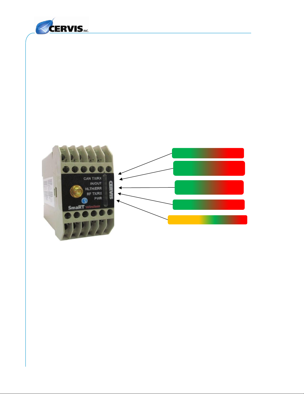
either horizontally or vertically to a standard 35 mm DIN rail. Five status/diagnostic LEDs—
illustrated in Figure 1—determine the state of the unit.
Figure 1. DIN-9H4R-2DI LEDs
DIN-9H4R-2DI Base Unit Features
•Input power +18 to +32 VDC (–24 V Option) +85 to +220 VAC (–120 V Option)
•900 MHz Channel-Hopping Direct Sequence Spread Spectrum (DSSS) Technology
•External antenna
•4 Form A Relay Contact outputs
•Can be mounted horizontally or vertically on a standard 35-mm DIN rail
•Size M3 (flat or Phillips) screw terminals
•Five LED diagnostic indicators
•Compact design, durable UL94V-0 rated ABS plastic enclosure
•RS-232 Port
•CAN Port
Green when any output is active;
Red when input is active
POWER –Amber OK; Red/Green Fault
DIN-9H4R-2DI
CAN TX/RX –TX Green; RX Red
Green pulse/sec –Health OK;
Red/Amber pulse/sec - Fault
RF TX/RX –TX Green; RX Red

Base Unit Manual
©2020 Cervis, Inc.
3
•Two active high discrete input channels
✓
Note: The two discrete input channels accept either +24 VDC or +120 VAC input signals.
The power supply (–24 V or –120 V) determines the signal range. Input channels are active
high and require both high and low signal inputs for channel.
SmaRT DIN-9H4R-2DI
U127.0.0
4
2.0 SmaRT DIN-9H4R-2DI Installation
Make sure the machine on which the base unit is to control is disabled during
installation.
The base unit enclosure and connectors are NOT rated for high pressure
washing. Doing so could damage the base unit or connectors.
Base unit mounting is left much to your discretion with the following guidelines:
•Make sure that the configuration diagrams supplied with the system are available.
•Always mount the unit away from any intense radio or electric disturbance sources.
•Mount the unit where you have enough room for your wiring connections.
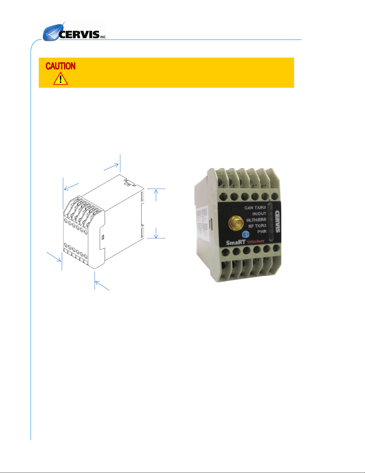
2.1 DIN-9H4R-2DI Base Unit Mounting Dimensions
Figure 2. DIN-9H4R-2DI Base Unit Mounting Dimensions
3.906"
1.717"
2.953"
Base Unit Manual
©2020 Cervis, Inc.
5
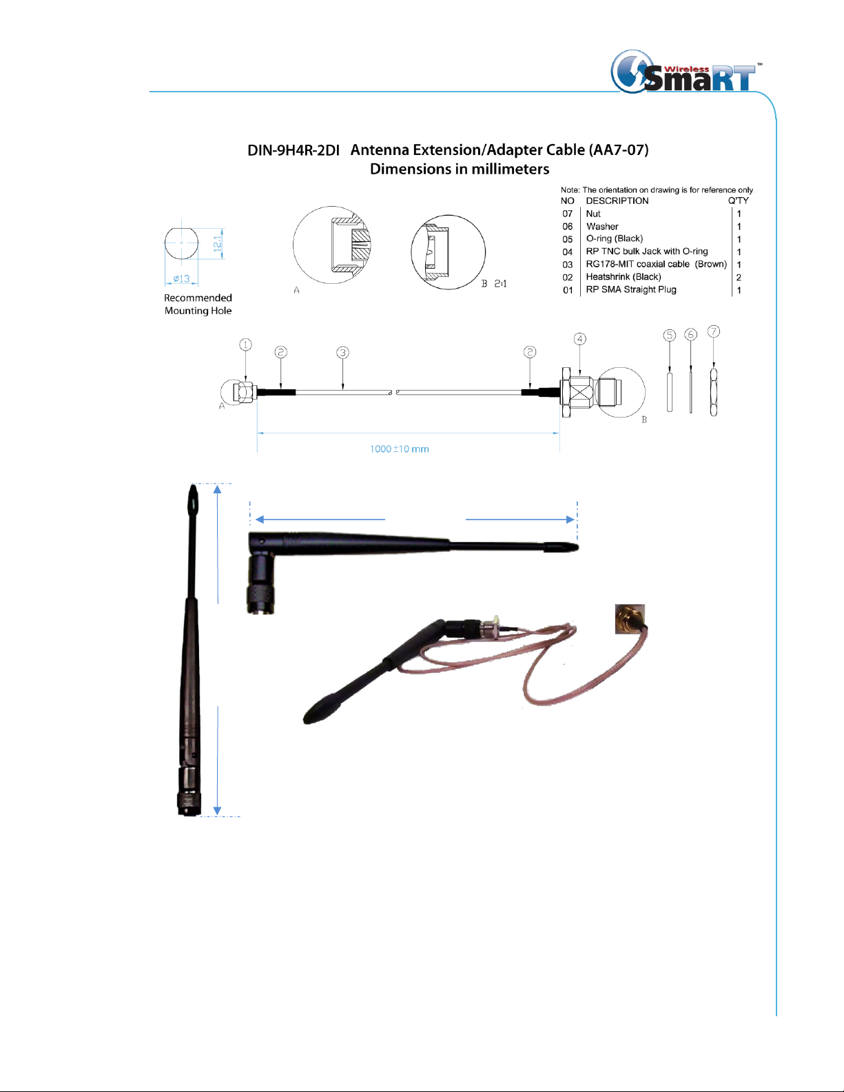
2.2 External Antenna Mounting
Figure 3. External Antenna Mounting Details
BB3-06 900 MHz Antenna and AA7-07 Extension/Adapter
183 mm (7.2")
212 mm (8.35")
SmaRT DIN-9H4R-2DI
U127.0.0
6
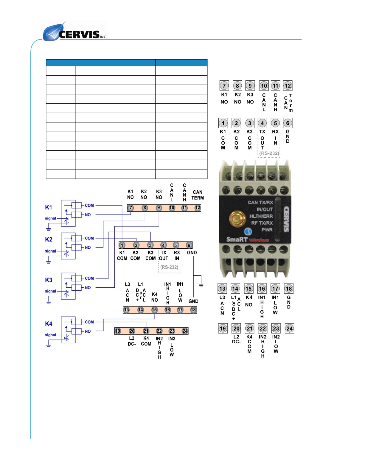
2.3 SmaRT DIN-9H4R-2DI Terminal Connections
Figure 4. DIN-9H4R-2DI Terminal Connections
Terminal
Description
Terminal
Description
1
K1 Common
13
L3 (AC N)
2
K2 Common
14
L1 (AC L or DC+)
3
K3 Common
15
K4 Normally Open
4
TX Out (RS-232)
16
Input 1 High
5
RX In (RS-232)
17
Input 1 Low
6
Gnd
18
Gnd
7
K1 Normally Open
19
No Connection
8
K2 Normally Open
20
L2 (DC-)
9
K3 Normally Open
21
K4 Common
10
CANL
22
Input 2 High
11
CANH
23
Input 2 Low
12
CAN-Term
24
No Connection
Table of contents
Popular Industrial Electrical manuals by other brands

Rexroth Indramat
Rexroth Indramat DURADRIVE SYSTEM200 Project planning manual

Abtech
Abtech HVJB Series Installation, operation & maintenance instructions

Murata
Murata GRM0335C1H8R1DA01 Series Reference sheet

SAF-HOLLAND
SAF-HOLLAND CBX 5415.5 Installation and operation manual

Eaton
Eaton Ulusoy HMH24-04 user manual

Newlong
Newlong NP-7H NSTRUCTION MANUAL/PARTS LIST

Murata
Murata GJM0335C1E4R4BB01 Series Reference sheet

Stahl
Stahl 8575/12 operating instructions

SI
SI Pegasus installation instructions

Murata
Murata GRM1555C1H2R7CA01 Seies Reference sheet

Murata
Murata GRM0225C1E6R4BA03 Series Reference sheet

Cooper Power Systems
Cooper Power Systems VXE15 Installation and operation instructions


