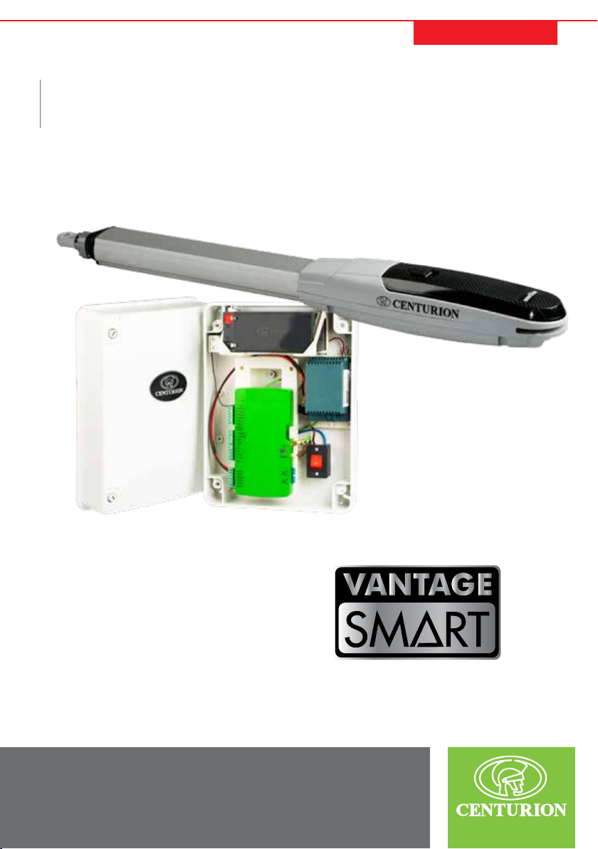
CENTURION SYSTEMS VANTAGE 400 SMART User manual

SWING GATE OPERATORS
Centurion Systems (Pty) Ltd
www.centsys.com
VANTAGE SMART
INSTALLATION MANUAL

After-sales
multi-language
Technical Support
Manufactures to
international
quality standard
ISO 9001:2015
100%
testing of
products
In-house
R&D
development
team
Centurion Systems (Pty) Ltd reserves the right to make changes to the product described in this
manual without notice and without obligation to notify any persons of any such revisions or changes.
Additionally, Centurion Systems (Pty) Ltd makes no representations or warranties with respect to
this manual. No part of this document may be copied, stored in a retrieval system or transmitted in any
form or by any means electronic, mechanical, optical or photographic, without the express prior written
consent of Centurion Systems (Pty) Ltd.
1986 1990 1995 1999 Today
Sales and technical support
to Africa, Europe, Asia,
the Americas, Australia
and the Pacic
Call Centre Operating Times
Live Chat support via MyCentsys
Pro Mobile Application
Monday to Friday
08h00 to 17h00 GMT+2,
Saturdays
08h00 to 14h00 GMT+2
Company Prole
ISO 9001:2015

page 3 www.centsys.com
1. INTRODUCTION
1.1. Important Safety Information
1.2. Lightning Protection
2. SPECIFICATIONS
2.1. Physical Dimensions
2.2. Technical Specications
2.3. Allowable Gate Masses
2.4. Wind Loads
3. PRODUCT IDENTIFICATION
4. REQUIRED TOOLS AND EQUIPMENT
5. NEW SITE INSTALLATION PREPARATION
5.1. General Considerations for the Installation
5.2. Determine Gate Opening Angle
5.3. Key Terms in this Section
5.4. Side Wall Limitation - Inward Opening
5.5. Cabling Requirements
5.6. Mounting the Wall Bracket
5.7. Mounting the Gate Bracket
5.8. Cabling Requirements
5.9. Critical Installation Checklist
6. OPERATOR INSTALLATION - INWARD OPENING
6.1. New Site Installations
6.2. Key Terms in this Section
7. OPERATOR INSTALLATION - OUTWARD OPENING
7.1. New Site Installations
Page 5
Page 6
Page 8
Page 9
Page 9
Page 9
Page 11
Page 12
Page 13
Page 14
Page 15
Page 15
Page 16
Page 17
Page 17
Page 16
Page 19
Page 21
Page 22
Page 23
Page 24
Page 24
Page 24
Page 24
Page 24
Contents

page 4 www.centsys.com
8. ELECTRICAL SETUP
8.1. Secure Vx SMART Wallbox to the Wall
8.2. Wiring
8.2.1. Wiring Diagram Symbols
8.2.2. Wiring the Master Operator
8.2.3. Wiring the Slave Operator
8.2.4. Wired Closing Safety Baems (i5)
8.2.5. Double Wired Closing Safety Beams (i5)
8.2.6. Wired Opening Safety Beams (i5)
8.2.7. Wired Opening Safey Beams (PHOTON)
8.2.8. Double Wired Closing Safety Beams (PHOTON)
8.2.9. Wired Opening Safety Beams (PHOTON)
8.2.10. PHOTON SMART Wireless Beams
8.2.11. GLX900 Electronic Lock
8.2.12. Wiring for MagLock to Vx SMART Controller
8.2.13. Status LED
8.2.14. External Radio Receiver & Loop Detector
8.2.15. Holiday Lockout Keyswitch / Keypad
8.2.16. Pedestrian Keyswitch
8.2.17. G-ULTRA to Vx SMART Controller
8.2.18. Solar Panel
8.2.19. Pillar Light Pushbutton - Normally Open
8.2.20. Pillar Light Wiring
8.3. Fuse Protection
8.4. Commissioning the System
9. INSTALLATION HANDOVER
10. WARRANTY INFORMATION
Page 35
Page 35
Page 36
Page 37
Page 38
Page 38
Page 39
Page 39
Page 40
Page 40
Page 41
Page 41
Page 42
Page 42
Page 43
Page 44
Page 44
Page 45
Page 45
Page 46
Page 46
Page 47
Page 47
Page 48
Page 48
Page 49
Page 50
CONTENTS
Icons used in this manual
This icon indicates tips and other information that could be useful during the
installation.
This icon denotes variations and other aspects that should be considered during
installation.
This icon indicates warning, caution or attention! Please take special note of
critical aspects that MUST be adhered to in order to prevent injury.

page 5 www.centsys.com
INTRODUCTIONSECTION 1
1. INTRODUCTION
The VANTAGE SMART linear swing gate motor, available in two models with actuation
strokes of 400mm and 500mm, respectively, has been designed to automate a wide variety
of swing gates, from single or double light-domestic gates to heavy industrial double swing
gates.
The fail-safe and fully-redundant Position and Collision Detection System has been designed
and tested to set the standard in safety of operation and to provide an unparalleled level of
reliability and durability in operation.
The gate Travel Limits are managed by a sealed opto-electronic system that has been
designed not only to ensure ultra-reliable operation, but also to ensure precise position and
trajectory control. This enables very accurate and reliable collision detection to ensure safe
operation even under trying conditions.
This guide covers the mechanical installation of your new VANTAGE SMART swing gate
operator.
Advanced features of the Vx SMART logic controller include:
• Interactive graphic user interface via a smartphone application
• Automated setup of gate endpoints (limits)
• Independently-adjustable motor speed in both opening and closing directions
• Fail-safe collision detection and auto-reverse (adjustable sensitivity)
• Smooth, adjustable start/stop (ramp-up/ramp-down)
• Multiple operational modes
• Selectable, adjustable Autoclose
• Pedestrian (partial) opening
• Positive Close Mode
• Supports up to three sets of Photon SMART Safety beams
• Independent safety inputs for opening and closing beams (wired)
• Automatic beam test for both opening and closing beams (wired)
• Advanced lightning/surge protection
• Onboard NOVA code-hopping radio receiver with full channel-mapping capability
(1500 MyCentsys Remote users1)
1. Multiple buttons per remote can be used.
VANTAGE SMART swing gate operators can be installed on both inward-
and outward-opening swing gates. Please see the relevant sections for
each type of installation, paying attention to any site preparation that
needs to be made before the operators are installed.

page 6 www.centsys.com
1.1. Important Safety Information
ATTENTION!
To ensure the safety of people and possessions, it is important that
you read all of the following instructions.
Incorrect installation or incorrect use of the product could cause
serious harm to people.
The installer, being either professional or DIY, is the last person on
the site who can ensure that the operator is safely installed and that
the whole system can be operated safely.
INTRODUCTIONSECTION 1
Warnings for the Installer
CAREFULLY READ AND FOLLOW ALL INSTRUCTIONS before installing the
product.
• All installation, repair, and service work to this product must be carried out by a
suitably qualied person
• This appliance is not intended for use by persons (including children) with reduced
physical, sensory or mental capabilities, or lack of experience and knowledge, unless
they have been given supervision or instruction concerning use of the appliance by a
person responsible for their safety
• Do not activate your gate unless it is in view and you can determine that its area of
travel is clear of people, pets, or other obstructions
• NO ONE MAY CROSS THE PATH OF A MOVING GATE —
always keep people and objects away from the gate and its area of travel
• NEVER LET CHILDREN OPERATE OR PLAY WITH THE GATE CONTROLS
• Secure all easily-accessed gate opener controls in order to prevent unauthorised use
of the gate
• Do not in any way modify the components of the automated system
• Do not install the equipment in an explosive atmosphere: the presence of ammable
gases or fumes is a serious danger to safety
• Before attempting any work on the system, turn o electrical power to the operator
and disconnect the batteries
• The Mains power supply of the automated system must be tted with an all-pole
switch with contact opening distance of 3mm or greater; use of a 5A hydraulic
breaker with all-pole circuit break is recommended
• Make sure that an earth leakage circuit breaker with a threshold of 30mA is tted
upstream of the system
• Never short-circuit the battery and do not attempt to recharge the batteries with
power supply units other than that supplied with the product, or manufactured by
Centurion Systems (Pty) Ltd

page 7 www.centsys.com
INTRODUCTIONSECTION 1
• Make sure that the earthing system is correctly constructed and that all metal parts of
the system are suitably earthed
• Safety devices must be tted to the installation to guard against mechanical
movement risks such as crushing, dragging and shearing
• Always t the warning signs visibly to the inside and outside of the gate
• The installer must explain and demonstrate the manual operation of the gate in case
of an emergency and must hand over the User Guide/Warnings to the user
• The installer must explain these safety instructions to all persons authorised to use
this gate, and be sure that they understand the hazards associated with automated
gates
• Do not leave packing materials (plastic, polystyrene, etc.) within reach of children as
such materials are potential sources of danger
• Dispose of all waste products like packing materials, worn-out batteries, etc.,
according to local regulations
• Always check the obstruction detection system, and safety devices for correct
operation
• Neither Centurion Systems (Pty) Ltd, nor its subsidiaries, accepts any liability caused
by improper use of the product, or for use other than that for which the automated
system was intended
• This product was designed and built strictly for the use indicated in this
documentation; any other use, not expressly indicated here, could compromise the
service life/operation of the product and/or be a source of danger
• Everything not expressly specied in these instructions is not permitted
WARNING! WARNING! WARNING! WARNING! WARNING!
MOVING GATE CAN CAUSE SERIOUS INJURY OR DEATH!
KEEP CLEAR! GATE MAY MOVE AT ANY TIME!
DO NOT ALLOW CHILDREN TO OPERATE THE GATE OR PLAY IN THE
NEAR VICINITY OF THE GATE.
KEEP CLEAR!
GATE MAY MOVE AT ANY TIME!
SAFETY
FIRST
Never run the operator directly from the battery!
Doing so will cause damage to the operator.
Only run the operator from the Vx SMART Controller.

page 8 www.centsys.com
The electronic controller utilises the same proven surge protection philosophy that is
used in all our products. While this does not guarantee that the unit will not be damaged
in the event of a lightning strike or power surge, it greatly reduces the likelihood of such
damage occurring. The earth return for the surge protection is provided via the mains
power supply earth and/or earth spike located next to the operator.
INTRODUCTIONSECTION 1
1.2. Lightning Protection
In order to ensure that the surge protection is eective, it is essential
that the unit is properly earthed.

page 9 www.centsys.com
SPECIFICATIONSSECTION 2
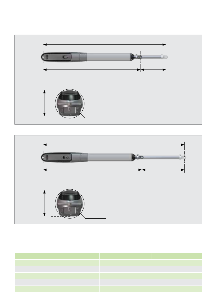
FIGURE 1. VANTAGE 400 SMART PHYSICAL DIMENSIONS
FIGURE 2. VANTAGE 500 SMART PHYSICAL DIMENSIONS
2. SPECIFICATIONS
2.1. Physical Dimensions
1. The current values can be used to determine current consumption for battery life backup calculations.
1370mm (extended)
1570mm (extended)
400mm
extended
piston stroke
500mm
extended
piston stroke
970mm (retracted)
1070mm (retracted)
Ø100mm
Ø100mm
95mm95mm
VANTAGE 400 SMART VANTAGE 500 SMART
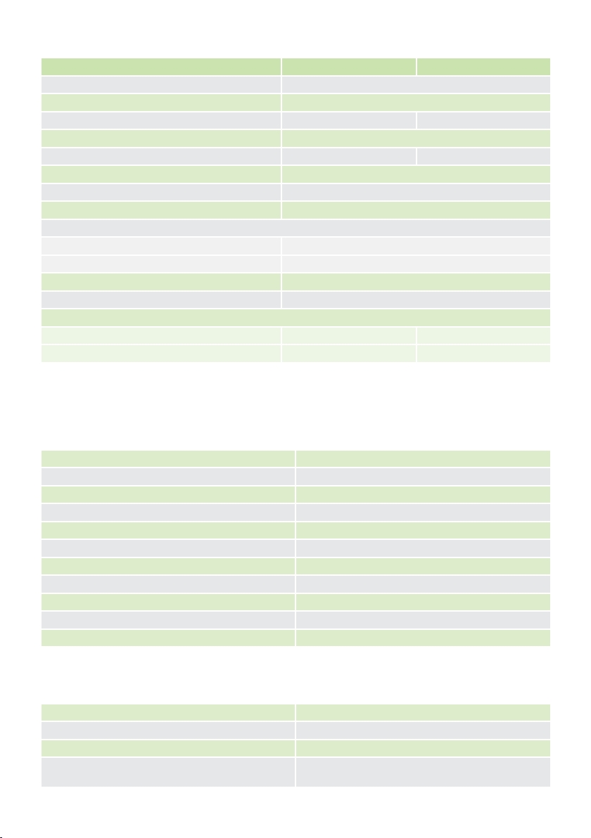
Input voltage 90V - 240V AC ± 10%, 50/60Hz
Motor voltage 12V DC
Motor power supply Battery-driven (standard capacity - 7.2Ah)1
Battery charger21.8A @ 13.8V
Current consumption (Mains) 170mA
2.2. Technical Specications
2.2.1. Main Operator

page 10 www.centsys.com
SPECIFICATIONSSECTION 2
Maximum motor current per channel 35A (fused)
Maximum input voltage 14.4V DC
Standby current draw 3A DC / AC (10 Seconds)
Maximum solenoid current draw 2A DC1
Maximum auxillary output current 3A (Resettable Electronic Fuse)
Collision detection Current sense and optical
Position and trajectory control Optical
Temperature range -20°C to +60°C
Onboard receiver type Code-hopping multichannel
Receiver code storage capacity 1500 transmitters
Receiver frequency 433MHZ
2.2.2. SMART Controller
1. Can increase battery capacity for longer standby times.
2. Can operate o a solar supply, consult your reseller for assistance.
3. Assumes a full stroke of operator is used.
4. Each operator comes with a unique set of keys.
5. Based on 25°C ambient temperature and unit not in direct sunlight.
1. Limited by charger, ensure that load does not prevent battery from fully charging.
Continuous current draw should ideally be less than 500mA but must not exceed 1A.
6. Based on an operator push force of less than 50% of rated.
7. Based on double kit excluding Infrared Safety Beams.
8. Single kit contains one operator and Wall Box.
9. Double kit contains two operators and one Wall Box.
TABLE 1
TABLE 2
VANTAGE 400 SMART VANTAGE 500 SMART
Current consumption (Motor rated at load) 15A - maximum
Operator push force - maximum 250kgf
Operator stroke 400mm 500mm
Piston extention / retraction speed 28mm/sec (variable)
Typical gate opening time314.3 sec 17.8 sec
Manual override Key release4
Maximum number of operations per day 250
Duty cycle - Mains present5 6 50%
Operations in standby with 7.2Ah battery7
Half day 70
Full day 58
Collision sensing Electronic
Operating temperature range -15°C to +50°C
Mass of unit packed (excluding battery)
Single kit88.5kg 9kg
Double kit914kg 15kg
2.2.1. Main Operator (Continued)
Nominal input voltage 90V - 240V AC ±10% @ 50/60Hz
AC current draw (maximum) 170mA
Temperature range -20°C to +60°C
Battery charger output current
(dependant on PSU input voltage)
90V AC input: 1.2A @ 13.8V
240V AC input: 1.8A @ 13.8V
2.2.3. Power Supply
TABLE 3

This manual suits for next models
1
Table of contents
Other CENTURION SYSTEMS Gate Opener manuals